Systems
Crimson
Introduction
General
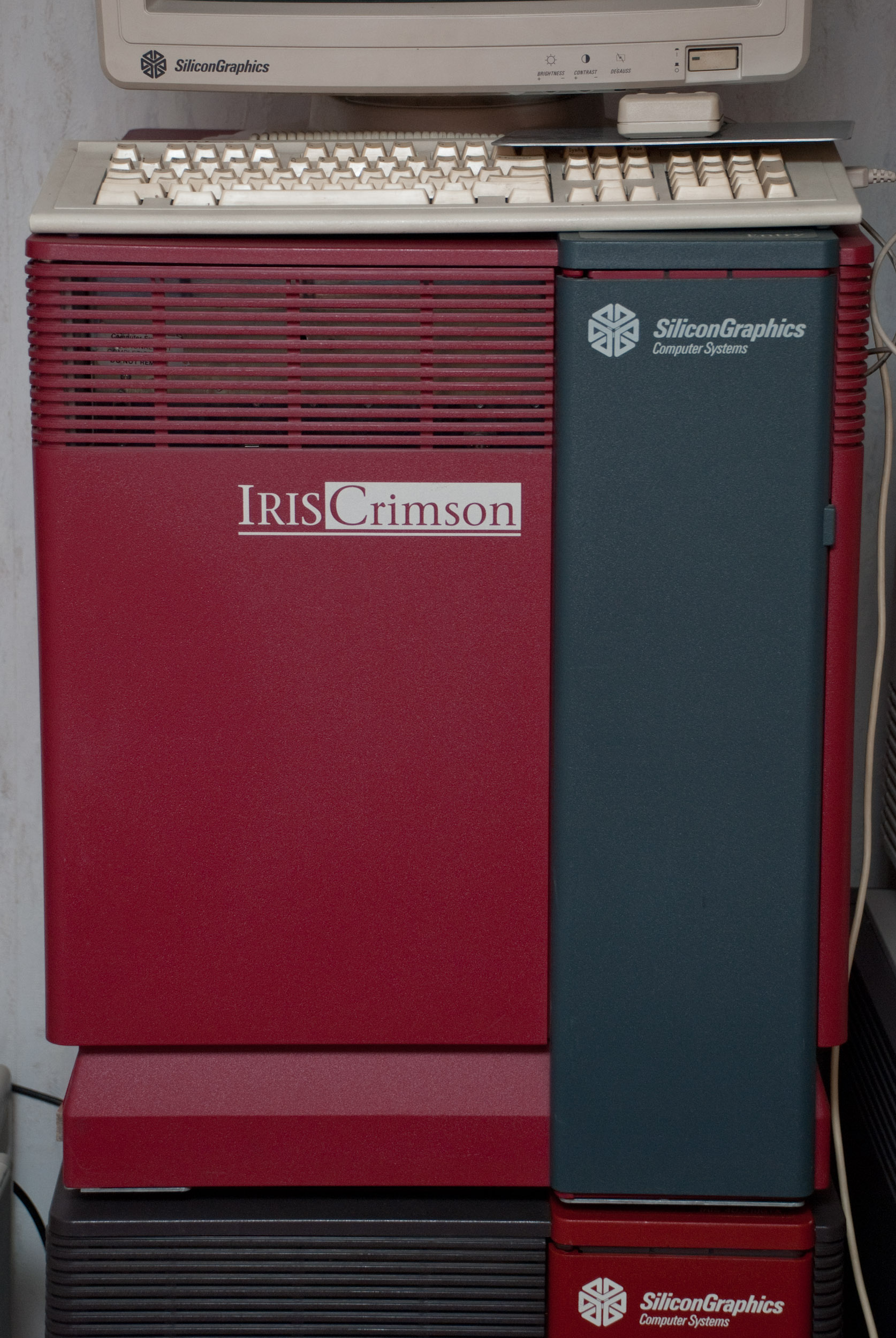
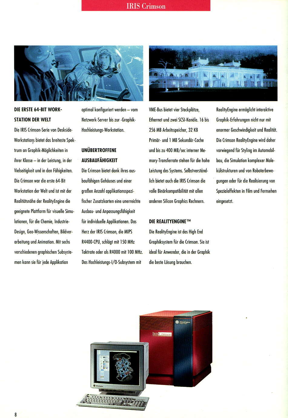
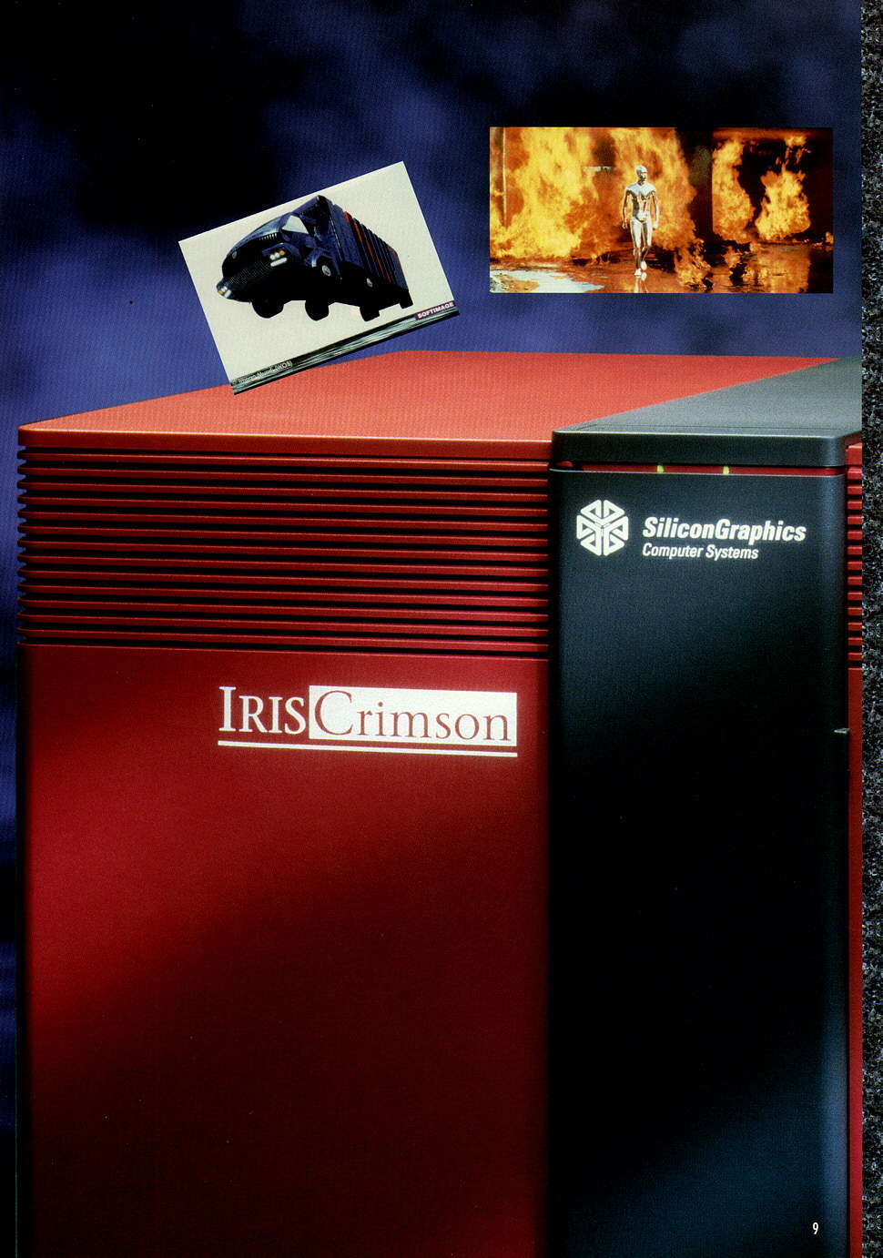
SGI Crimson front.
The IRIS Crimson was the first Silicon Graphics computer that featured the new 64bit superscalar microprocessor R4000.The system has become somewhat popular after it was featured in the movie Jurassic Park. Silicon Graphics has even made a limited edition of the crimson which featured a "Jurassic Classic" print on the gray front door.
The IRIS Cromson can be considered the last of the 4D/PowerSeries systems. It basically is a PowerSeries system with a different CPU and memory subsystem to support the R4000 CPU. This is why the 4D/510 was a possible upgrade path from an older PowerSeries system which involved swapping the CPU and memory boards of the older PowerSeries for the new Crimson mainboard.
            R4000/100     R4400/150
---------------------------------------
MIPS           85           120 (est.)
MFLOPS         16            22 (est.)
SPEC89         70           100 (est.)
SPECint92      58.3          86.0
SPECfp92       61.5          93.2
Models
| Model | CPU board | CPU | Chassis |
|---|---|---|---|
| Crimson R4000 | IP17 | MIPS R4000 100 MHz | Deskside |
| Crimson R4400 | IP17 | MIPS R4400 150 MHz | Deskside |
History
- 1992, January
- Crimson R4000 introduced. Prices for systems in a basic configuration in the USA were approximately: 27,900 for the server, 42,900 for a Crimson/Elan and 69,900 for a Crimson/VGX.
- 1992
- RealityEngine debut
- 1997, December
- End of Production
- 2004, June
- End of Service
Processor
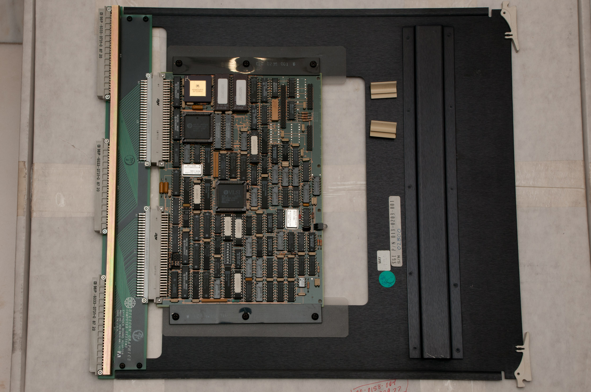
IP17 Mainboard
| CPU Board | Processor | Clockspeed | Cache (d/i) | Cache (2nd) | Floating Point |
|---|---|---|---|---|---|
| IP17 | R4000 | 100 MHz | 8KB / 8KB | 1MB | R4000 onboard |
| IP17 | R4400 | 150 MHz | 16KB / 16KB | 1MB | R4400 onboard |
On Crimson systems only one IP17 Mainboard is supported. In deskside systems it is also phyically impossible to use the second CPU slot which it has inherited because the Crimson chassis is the same as the PowerSeries chassis including it's backplane.
All memory has to be installed on the IP17 mainboard. Additional MC2 boards are not recognized by the system.
Memory
IP17 Mainboard
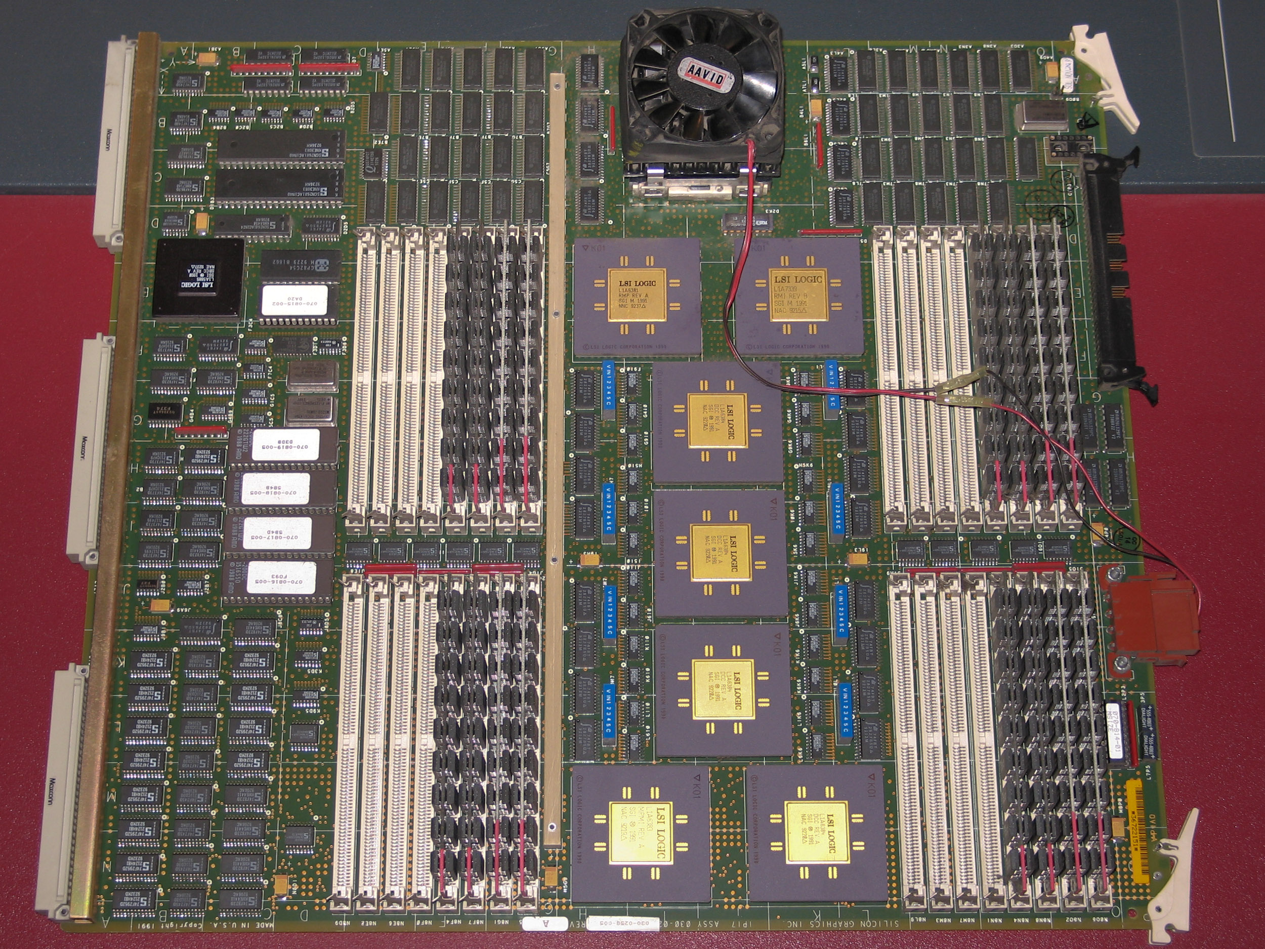
IP17 Crimson (R4000 100 MHz).
Type:                   proprietary 80pin SIMMs
Sockets:                32 (4 * 8 sockets)

Minimum configuration:  16 MB (8 * 2 MB modules)
Maximum configuration:  256 MB (32 * 8 MB modules)
The memory used on IP17 boards is of the same type as the PowerSeries memory used previously by SGI.
The memory on Crimson systems is located on the CPU board and can be accessed with lower latency than on other systems of this class as well as the predecessor PowerSeries. This can lead to a better application performance, especialle when a lot of cache misses occur during the excecution of a program. The Onyx in comparison has to access main memory via Everest bus, which will slow memory access down in comparison. So in rare cases a Crimson can outperform an Onyx. This obviously assumes that the machines run the same clockspeed and the program doesn't make use of the multiple CPUs on a Onyx.
MC2 Memory board
Although the Crimson shares many parts with the PowerSeries systems including the type of memory used, additional MC2 memory boards are not supported. All memory has to be installed on the IP17 mainboard.
Graphics
Options
The Crimson was available with a wide range of graphics hardware both originating from the PowerSeries family as well as from the line of Indigo workstations:
- Server (no Graphics)
- Entry Level Graphics
- Elan Graphics and relatet Graphics Options
- GTX/GTXB Graphics
- VGX/VGXT Graphics
- Reality Engine Graphics
Other
IO and SCSI
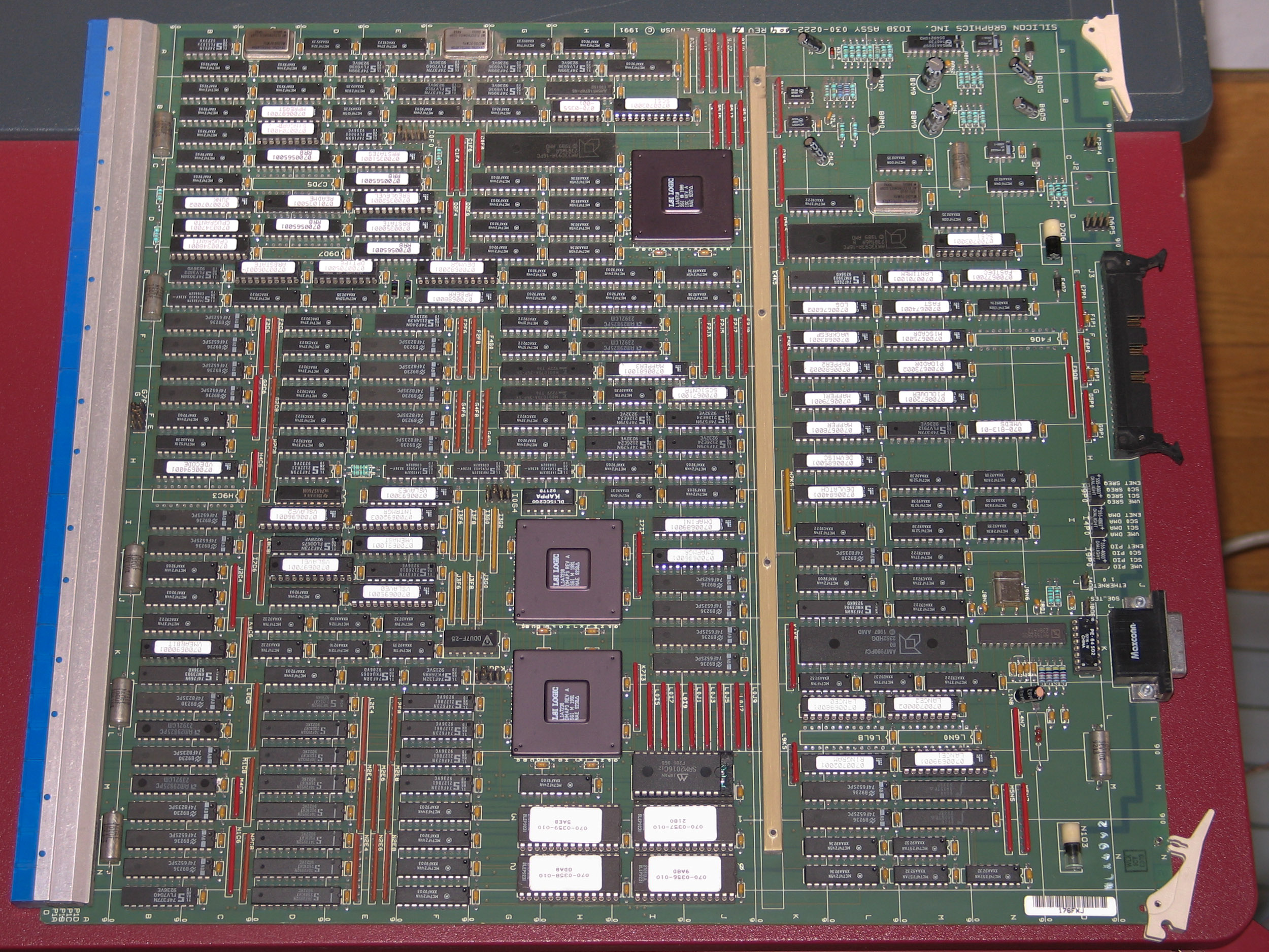
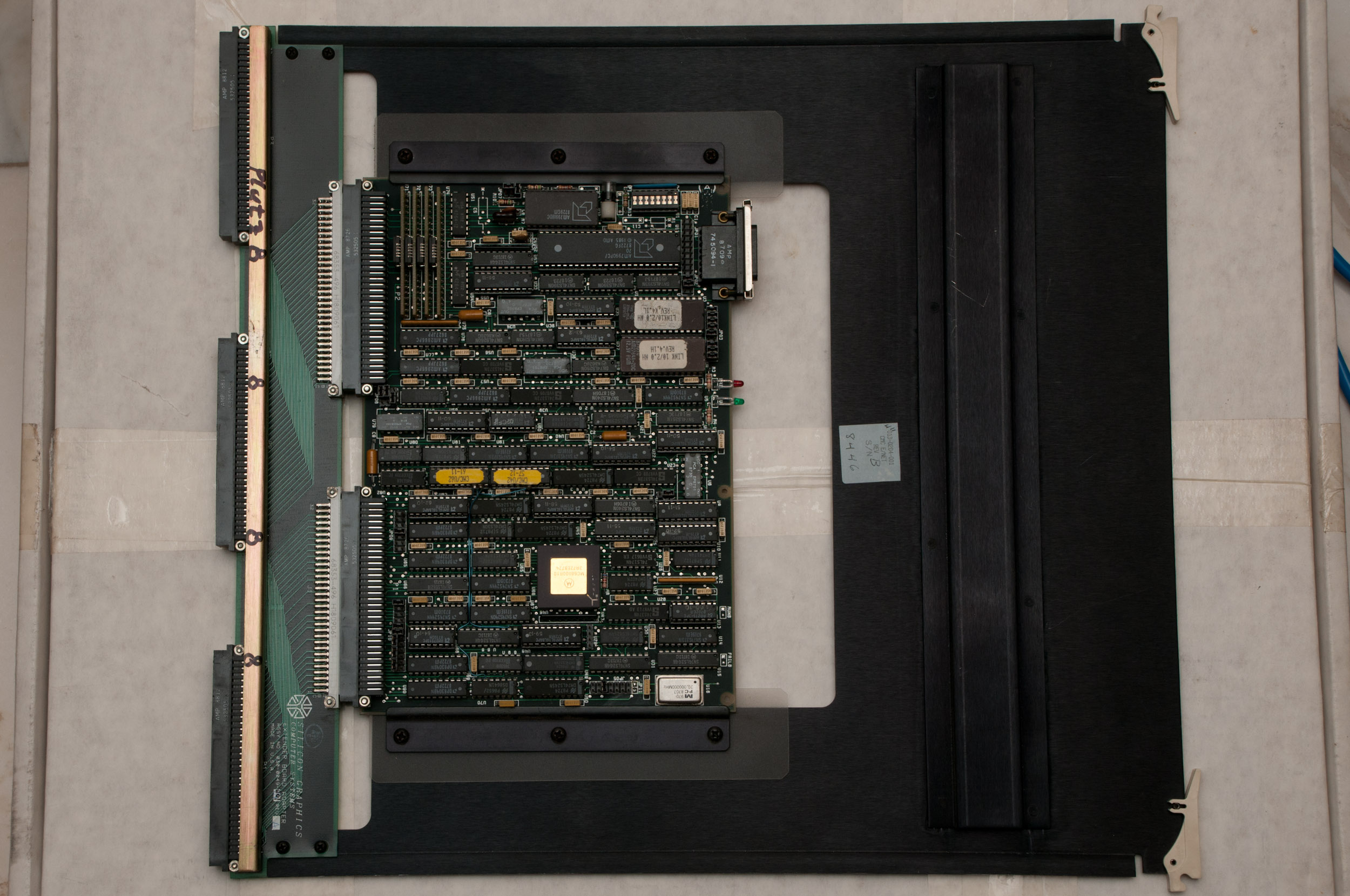
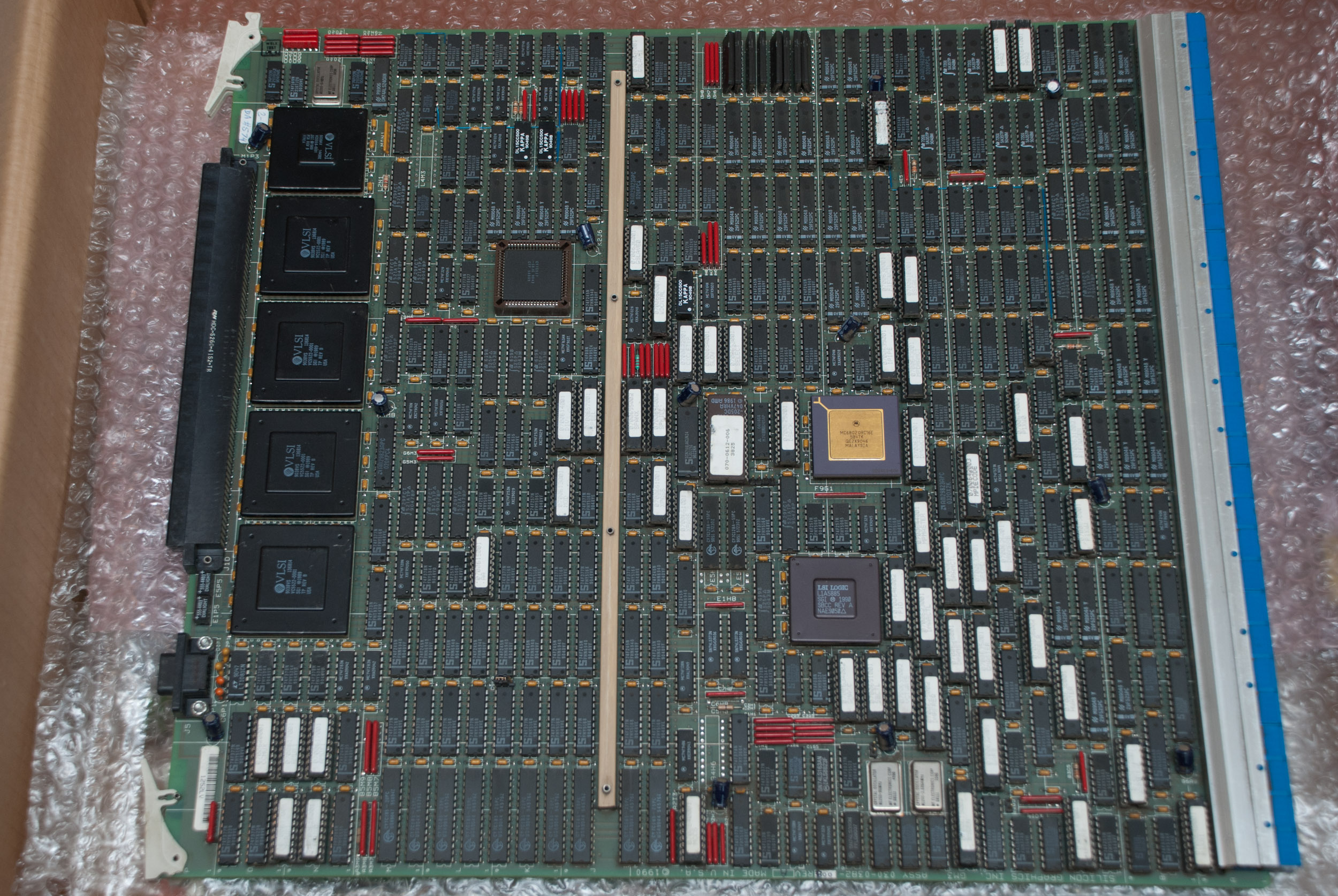
IO3B IO board for Crimson.
Crimson systems use an IO3B board as IO controller. All IO3B boards include one SCSI channel for internal use, a second that can be used via the IO panel and one Ethernet interface also for use via the IO panel.
The IO3B board can be used with PowerSeries (IP5, IP7, IP9, IP15) as well as Crimson (IP17) CPU boards. For Crimson support the jumper at position C0F0 needs to be placed on the pins located closest to the backplane connection.
2 SCSI channels are provided by the IO3B controller. The SCSI chipsets used are Western Digital WD33C93A. Using lv/xlv data can be distributed on logical volumes among several disks which may be attached to any of the SCSI channels in the system. This allows to use the bandwidth of both SCSI channels.
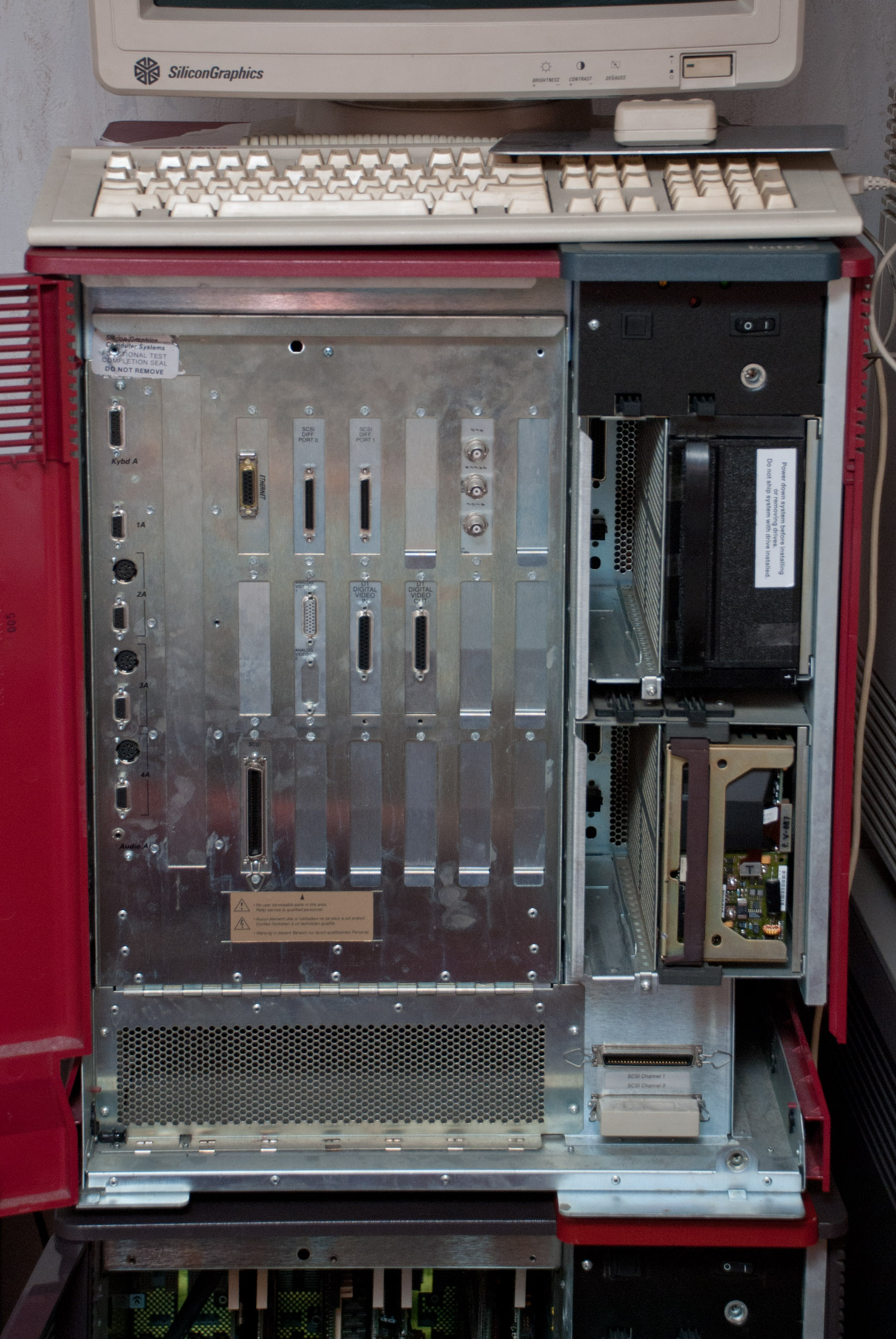
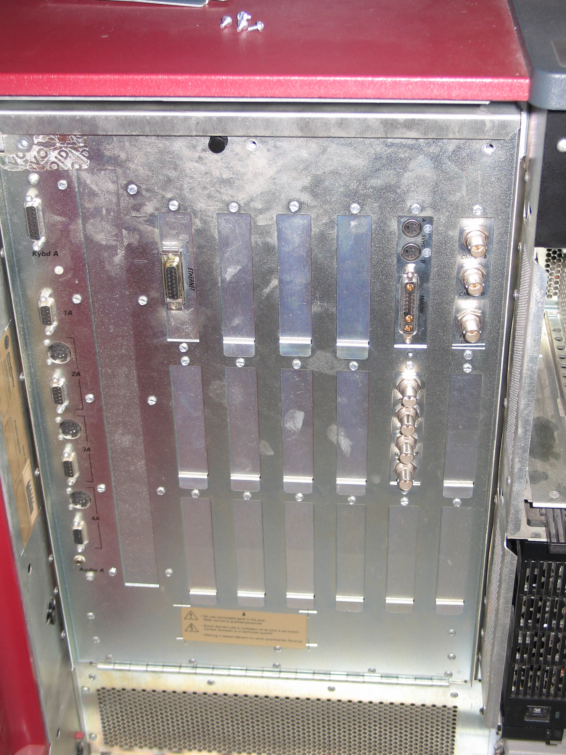
Connectors
All Crimson systems have at least:
- Drives:
- 2 centronics style SCSI connectors below the drivebay
- other SCSI connectors depending on cable/board configuration
- Networking:
- 1 ethernet interface (IO3B)
- Input/Output:
- Keyboard/Mouse
- 4 RS232 serial ports
- 3 Powered Peripheral Ports (8 Pin DIN)
- Graphics:
- 13W3, BNC or VGA depending on hardware installed
The actual connectors present on a Crimson system depend very much on the configuration of that system. With additional VME expansions (see below) a lot more and different I/O possibilities are available.
Options
Expansion Slots
For various expansions the Crimson systems have a single VME bus with 4 9U VME-32 slots.
General rules regarding VME setup:
- populate slots from slot #1 to slot #4
- remove BG/IACK jumper for every slot that cards are installed in
- if one slot is empty the BG/IACK jumpers must be set
The exception to this rule is the Genlock board which always goes in slot #4. If that is installed the genlock jumpers located to left of bottom connector of slot #4 must be in place.
Communications and IO Options
- Network interfaces (4 ethernet or token ring)
- HPPI interface
- FDDI interfaces (up to 4)
Drive Options
- Tape drives: 1/4" (QIC-150), 8mm Exabyte, DAT
- CD-ROM
- Internal disk drives with 1 or 2 GB (approx.)
- External disk drives
Video Options
- Broadcast Video Options
- CG2 / CG3
A graphics output option for G, TG, 8-bit and 12-bit graphics on the Personal Iris, as well as GT and GTX graphics on the PowerSeries. The output format is RGB and can be genlocked to an external video source. - Live Video Digitizer
- Video Creator
- Video Framer
- Video Lab
- Video Splitter
- Multi Channel Option
The Multi-Channel Option is similar to the VideoSplitter except that it has up to six channels and it supports the Reality Engine graphics only. It also supports various timing modes including NTSC and PAL.
Misc Options
- SCSI channels (narrow and HVD)
- 6-port serial card
Chassis
Dimensions
The original Crimson system comes in a deskside chassis that looks like the ones used on the PowerSeries systems but has red skins and it's top hat and drive door are gray ("Diehard 2").
width:     54 cm / 21"
height:    66 cm / 26"
depth:     74 cm / 29"

weight:    82 kg / 180 lbs
Details
Crimson frontpanel with optional SCSI, VGX Graphics and VideoLab.
The type of graphics option installed is denoted on a label on the top hat. There is no color code for parts as it was used on PowerSeries and Professional Iris systems.
Additionally there are 4D/510 models that have the dark PowerSeries chassis and have a label that says "R4000-50" and the graphics option on the top hat. These are PowerSeries machines that have been upgraded with a IP17 processor board and new IO3B controller board.
The IRIS Crimson contains 4 5.25" drivebays: 2 half height and 2 full height bays that can be used to install various SCSI drives mounted in a drivesled. For hints on the configuration see below.
Backplane Layout
In this section descibes only the Diehard 2 configuration (Single Tower Deskside). It will not cover the 4D/510 upgrade for Twin Tower and Rackmount PowerSeries systems. A setup for these systems is easy to guess from the information available.
| 1 | VME | The VME Slots have to be filled from left (#1) to right (#4) with no empty slots in-between. |
| 2 | VME | |
| 3 | VME | |
| 4 | VME | |
| 5 | IO | IO3B Controller |
| 6 | CPU | The CPU board of a Crimson is installed in slot #6, slot #7 remains empty. If the chassis is used to build an older Power Series machine both can be in use. |
| 7 | CPU | |
| 8 | MEM | This slot remains unused in Crimson systems because the memory is on the CPU board. However if the chassis is used to build another 4D series system this slot can be used for a memory board. |
| 9 | GFX | How the graphics slots are used depends on the type of graphics option. See Graphics section. |
| 10 | GFX | |
| 11 | GFX | |
| 12 | GFX | |
| 13 | GFX | |
| 14 | GFX |
Cooling and Power
The cooling fans under the cardcage differ between older and newer Crimsons. In old systems there are four blowers, in newer six. The 6-blower fan assembly is required for systems equipped with Reality Engine graphics, but was also used in Crimsons with other graphics options. Three of the six blowers are placed exactly under the graphics slots in the cardcage to provide improved cooling for the Reality Engine.
Apparently the Reality Engine draws also more power than the older graphics options. The standard Crimson powersupplies are rated at 1050W, the ones for loaded Crimsons with Reality Engine are rated at 1500W.
Status Display
The Single Tower has a yellow fault LED located newar the power switch. When the system is switched on both the fault LED and the green power LED are on. The yellow LED will no longer be lit if the system has passed POST. A single digit status LED is hidden behind the front panel.
Specials
Rebadged Systems
Relabeld Crimson systems were available from several companies, the most common being
- Siemens Nixdorf: Nothing is known about the design, the model was RW460.
Jurassic Classic
The "Jurassic Classic" systems are R4400/150 Crimsons that have a special logo incliding Jim Clarks signature on the drive door. This is a limited edition released due to the popularity of the Crimson gained by the feature film Jurassic Park.
Problems
Operating System
Choosing an operating system.
The Crimson is basically an R4000 fit to the Power Series architecture. When it was introduced IRIX version 4D1-4.x was the current operating system release. The first version with full R4000 Crimson support was 4D1-4.0.4, Reality Engine support followed in 4D1-4.0.5 or a subversion thereof.
General support for the Crimson can be found in the all platform releases of IRIX 5.x and IRIX 6.2 which is the last version that can be run on such a system. An exception to note is the support for GTX graphics which was dropped after IRIX 5.3.
The recommended operating system release for all Crimson systems is IRIX 6.2 unless GTX graphics is installed. In that case IRIX 5.3 would be the version to recommend. Please note though, that the IRIX 6.2 media have a bug that prevents it from being able to install on a blank disk (Crimson only).
Mode Switches
Where are "Mode" switches and what is their function?
The DIP switches are are on a PCA behind the frontpanel which holds the power/reset button as well as the status LEDs. Their function isn't covered in public documentation, but an old Usenet post lists at least some of the possible settings:
switch #s   hex   meaning
87654321    --    --
00000000    00    Default (all switches are closed)
10000001    81    PON Mode (drops into pon>)
10000010    82    SYMMON (unknown)
10000100    84    NODIAG (bypasses running power-on tests)
10001000    88    MPDEBUG (unknown)
Year 2000
Signs of failure: After a reboot the system thinks it is still in the 70s.
For this error there is no real fix - just some workarounds. The Crimson is not Y2K-ready and as its support ended with IRIX 6.2 SGI didn't spend too much time on looking at the specific problems. The error classifies as "annoying" but by all means it is not a fatal error. As soon as a valid time has been set the system keeps track of the correct time and date. The best solution would be to reset the date before any daemons are started, the second best to set the date when the machine has booted. In any case the Crimson should work without further problems... as far as IRIX 6.2 Y2K compliance goes. A timeserver (for example another SGI running timed) is very helpful and IRIX automatically sets the correct time and date on the Crimson.
SCSI configuration
The possibilities to configure the 2 SCSI channels of an IO3B in the Diehard 2 chassis.
At first it is important to understand where the SCSI cables come from and where they go to. The following short description tracks the cables beginning from the connectors below the drivebeays.
The cable from the top connector goes to the top drivebays and backplane SCSI connection, the cable from the bottom connector goes to the bottom drivebays and cardcage SCSI connection which can be plugged into the IO3B board.
- Jumpered configuration: Both bottom connectors are bridged using a short SCSI cable, the internal connector dangling from the cardcage top is NOT connected to the IO3B board. In this case all internal drives are on one SCSI chain (#0, the one routed via backplane). The external SCSI chain (#1) of the IO3B board can be used with externall connectors installed on the IO panel.
- Non-Jumpered (i.e. terminated) configuration: Both connectors at the bottom are terminated, the internal connector is attached to the IO3B board. In this case both SCSI channels (#0, #1) can be used internally (lower bays: #0, upper bays: #1). Instead of termination external SCSI devices may be attached to either chain using the connectors at the bottom of the machine.
The following table shows the number of devices that can be attached to the two SCSI channels in the 2 basic configurations:
Jumpered
   Channel #0:      internal 4 / external 0
   Channel #1:      internal 0 / external 7
Non-Jumpered (i.e. Terminated)
   Channel #0:      internal 2 / external 5
   Channel #1:      internal 2 / external 5
Pictures
Crimson Elan
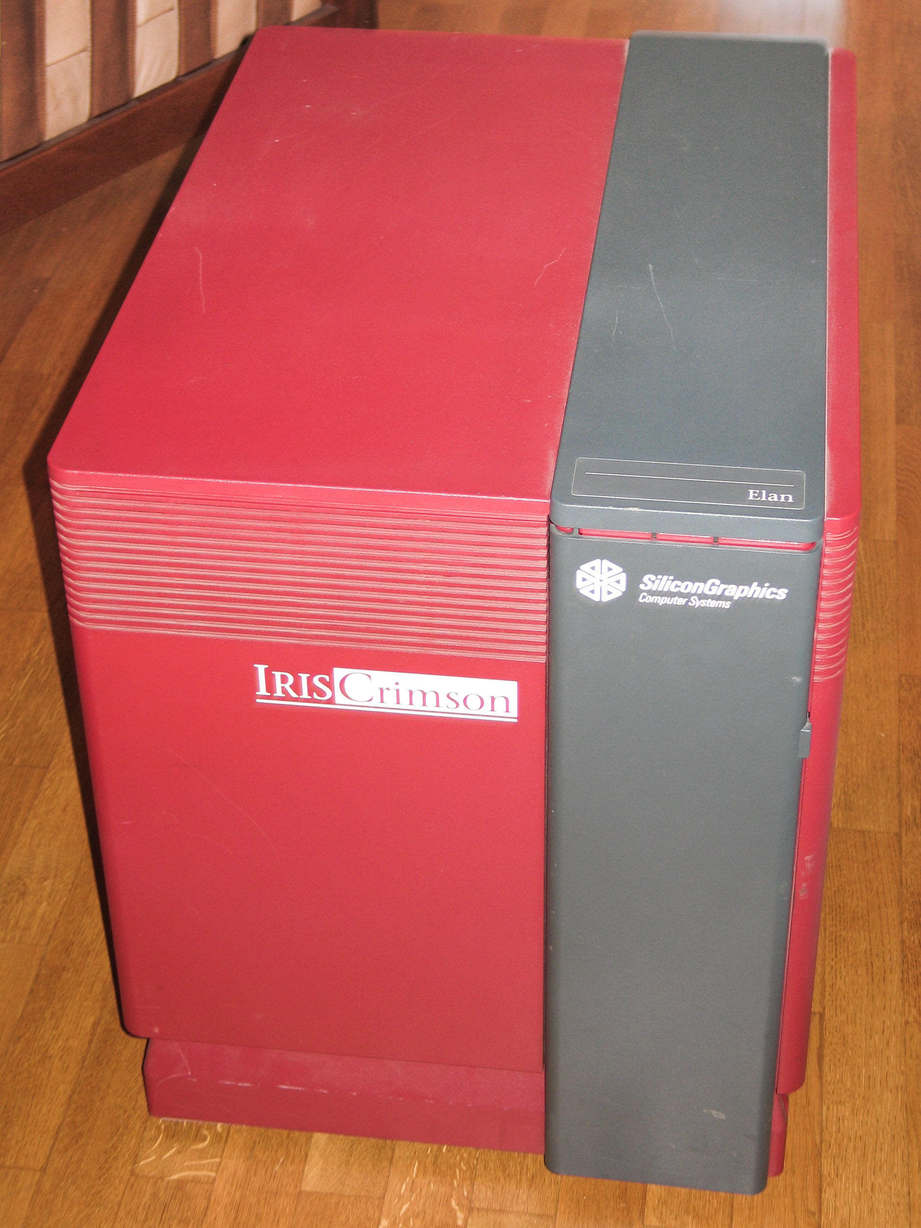
SGI Crimson front.
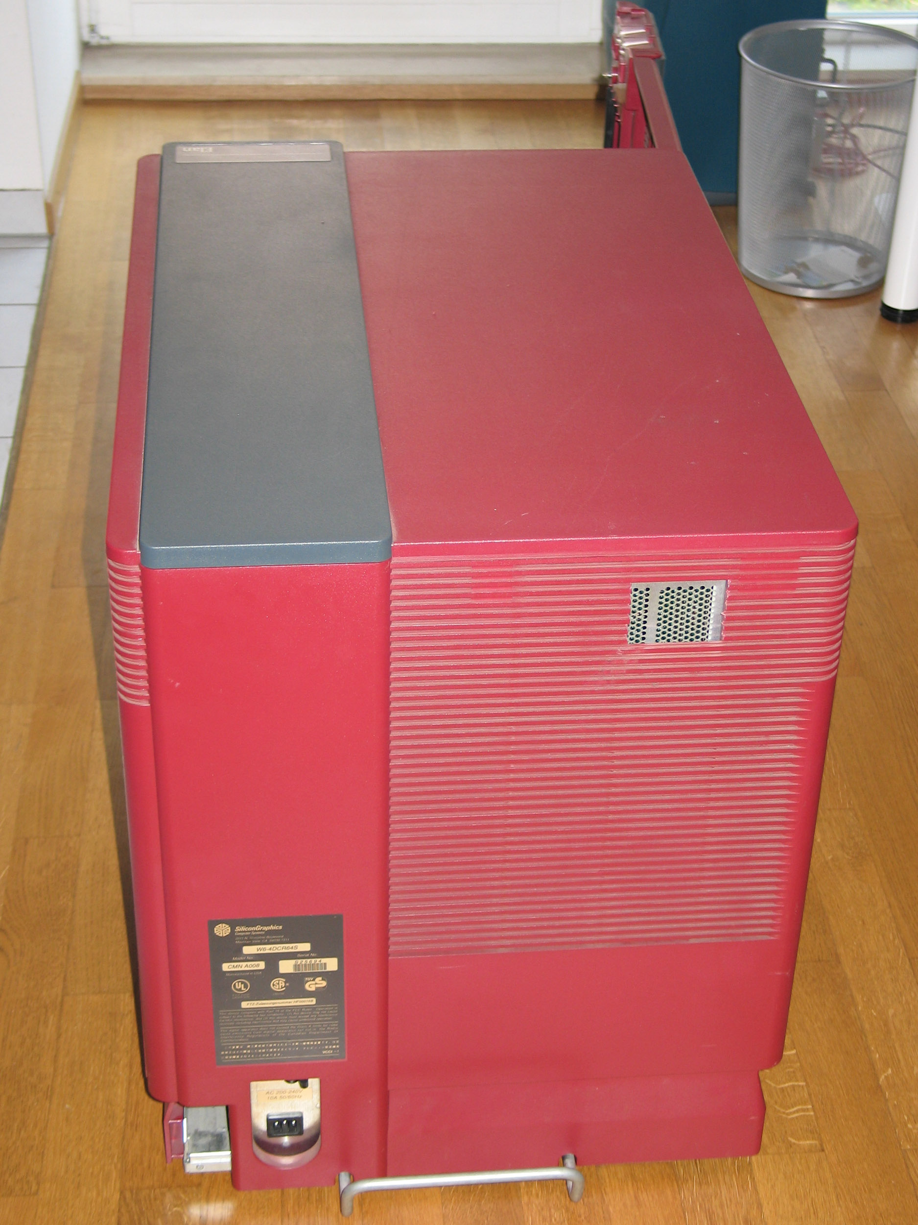
SGI Crimson back.
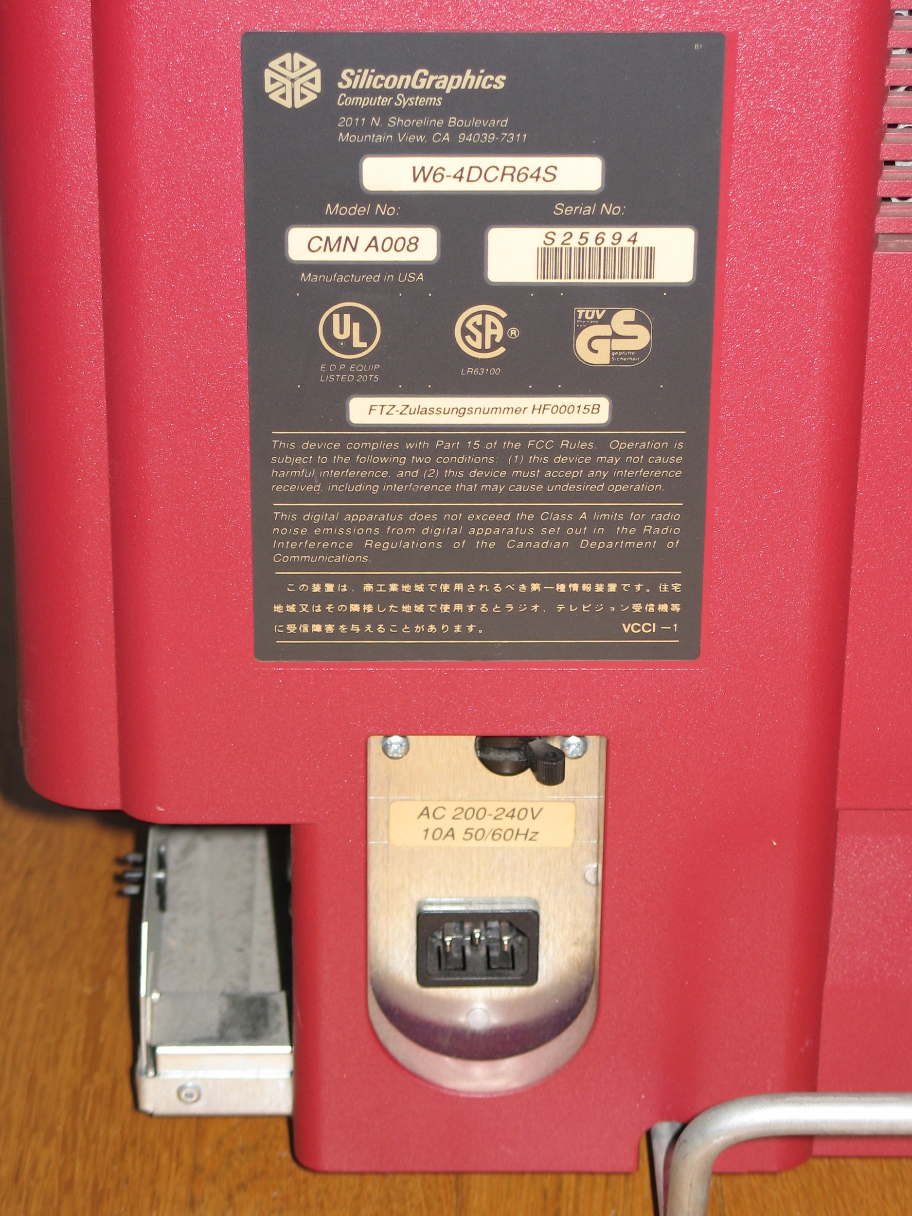
Crimson label.
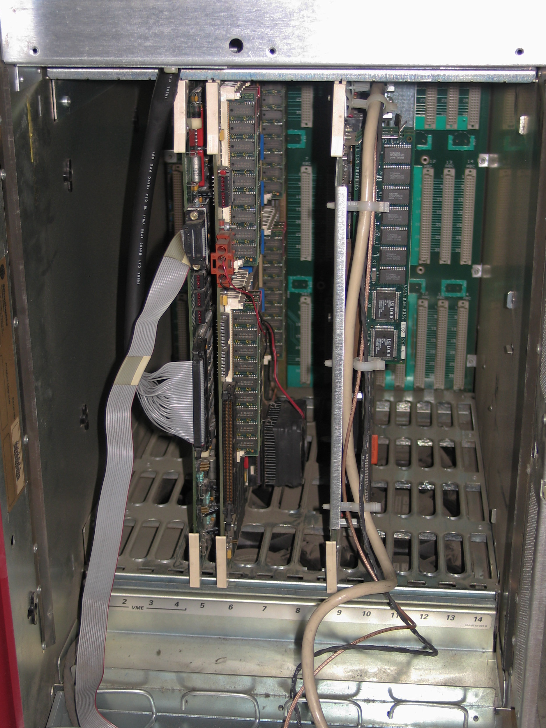
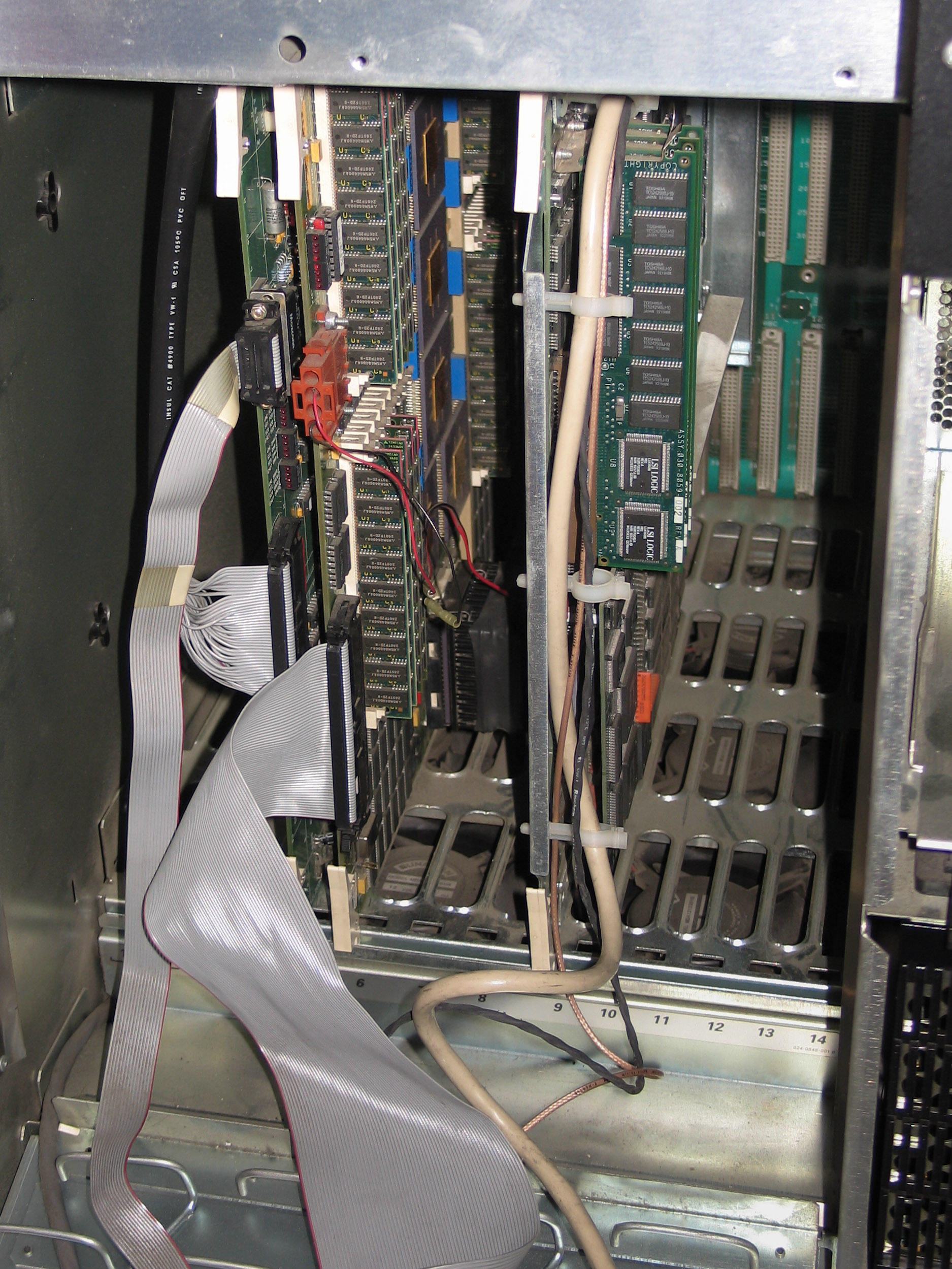
Crimson cardcage with IP17, IO3B and Elan Graphics
Crimson VGX
SGI Crimson front.
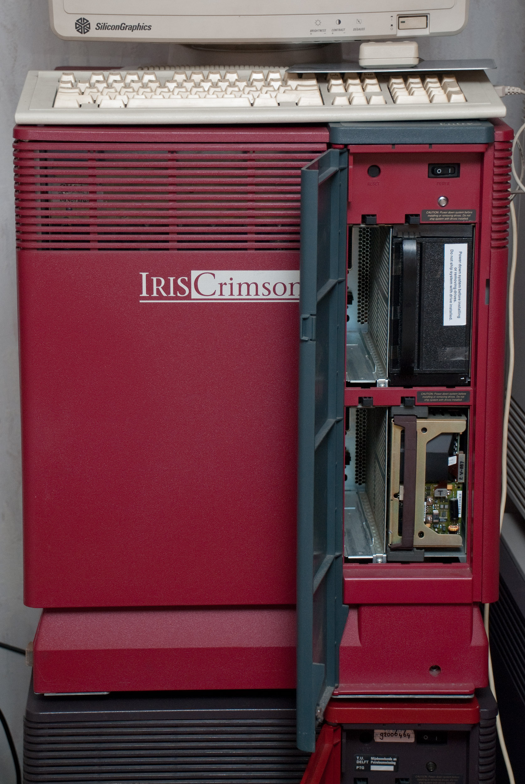
Front access to drive slots.
Crimson frontpanel with optional SCSI, VGX Graphics and VideoLab.

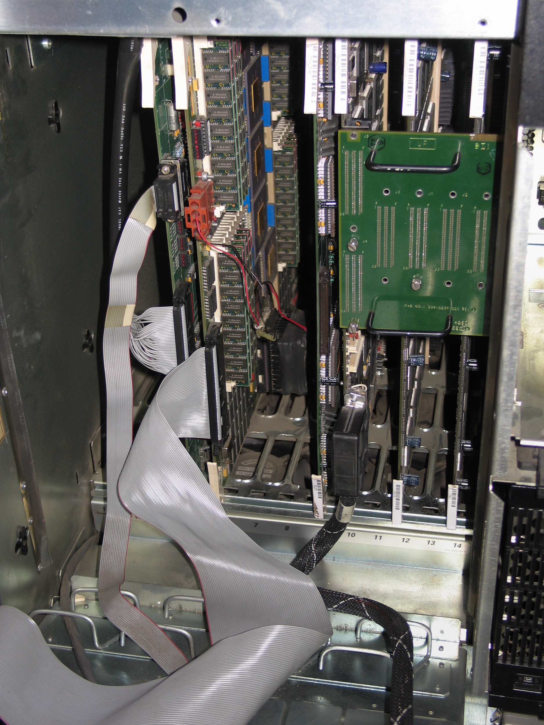
Crimson cardcage interior.
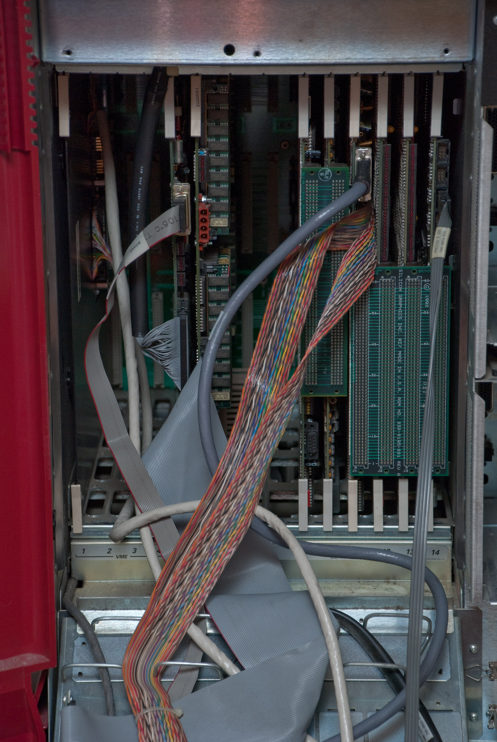
VME SCSI, IO3B, IP17 and VGX Graphics with VideoLab.
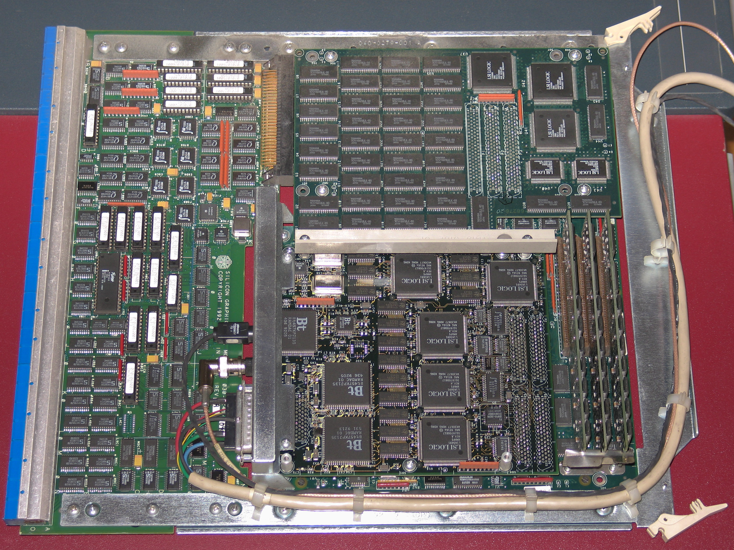
CPU
IP17 CPU board with MIPS R4000 (100MHz).
IO Boards
IO3B IO board for Crimson.
VME Options
CNC Ethernet
ESDI controller
Elan Graphics
Elan Graphics for Crimson and PowerSeries.
GTX Graphics
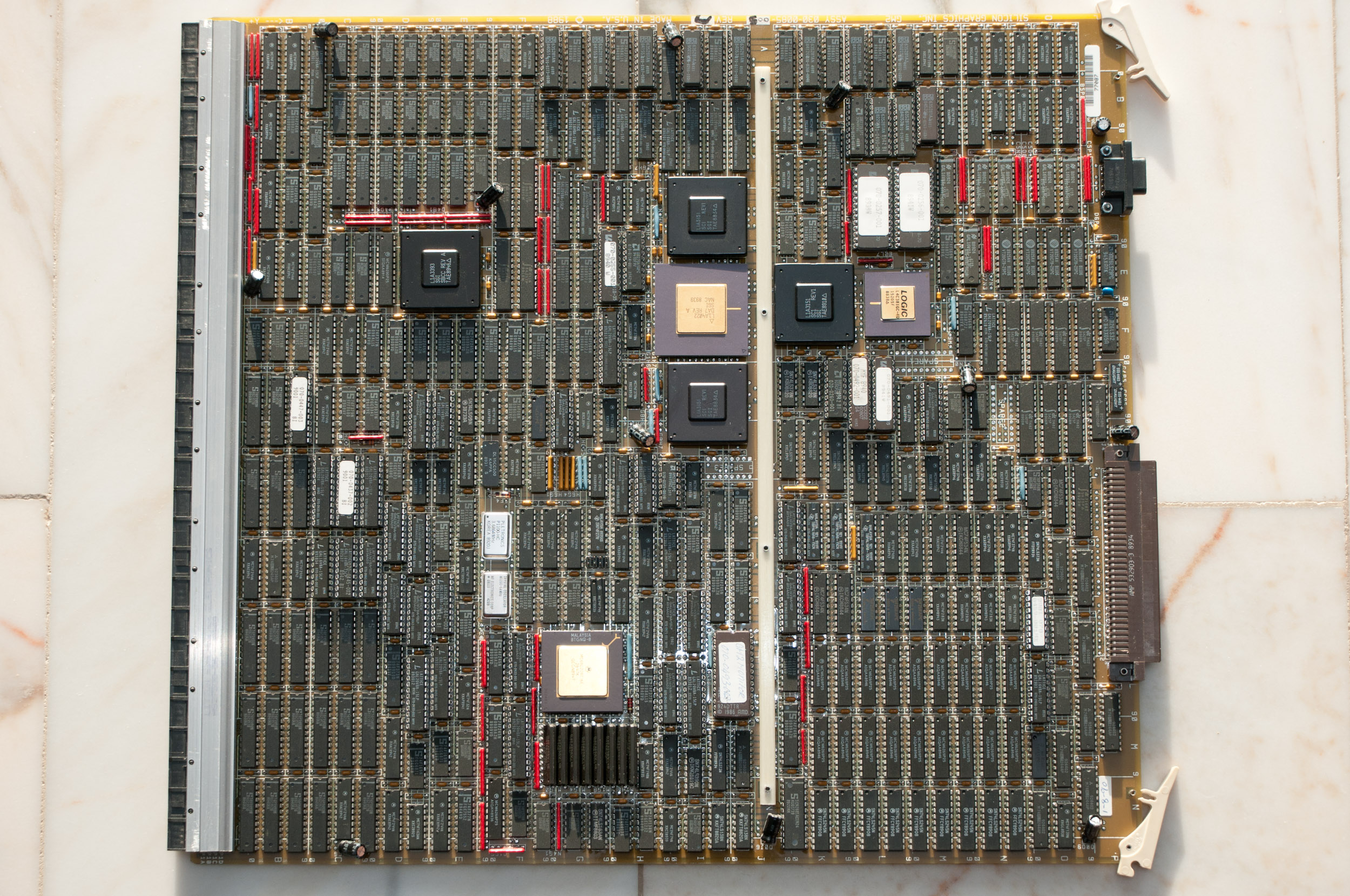
GTX GM2 Graphics Manager.
GTX GE4 Geometry Engine.
GTX RM1 Raster Manager.
GTX RM1 Raster Manager.
GTX RV1.5 Raster Video.
GTX connector.
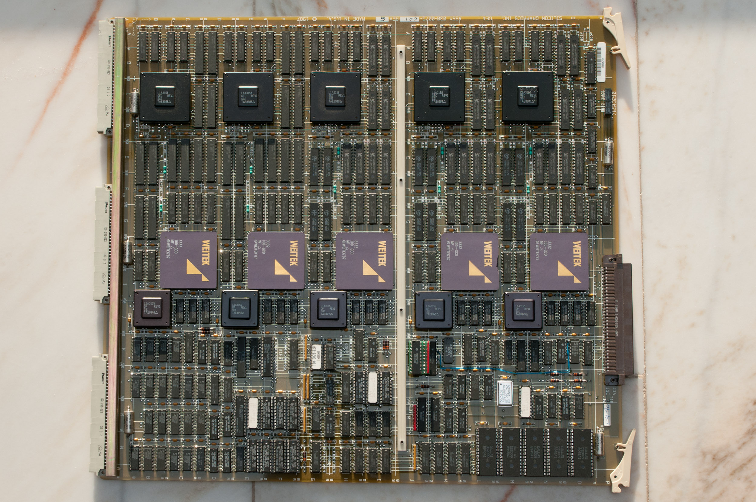
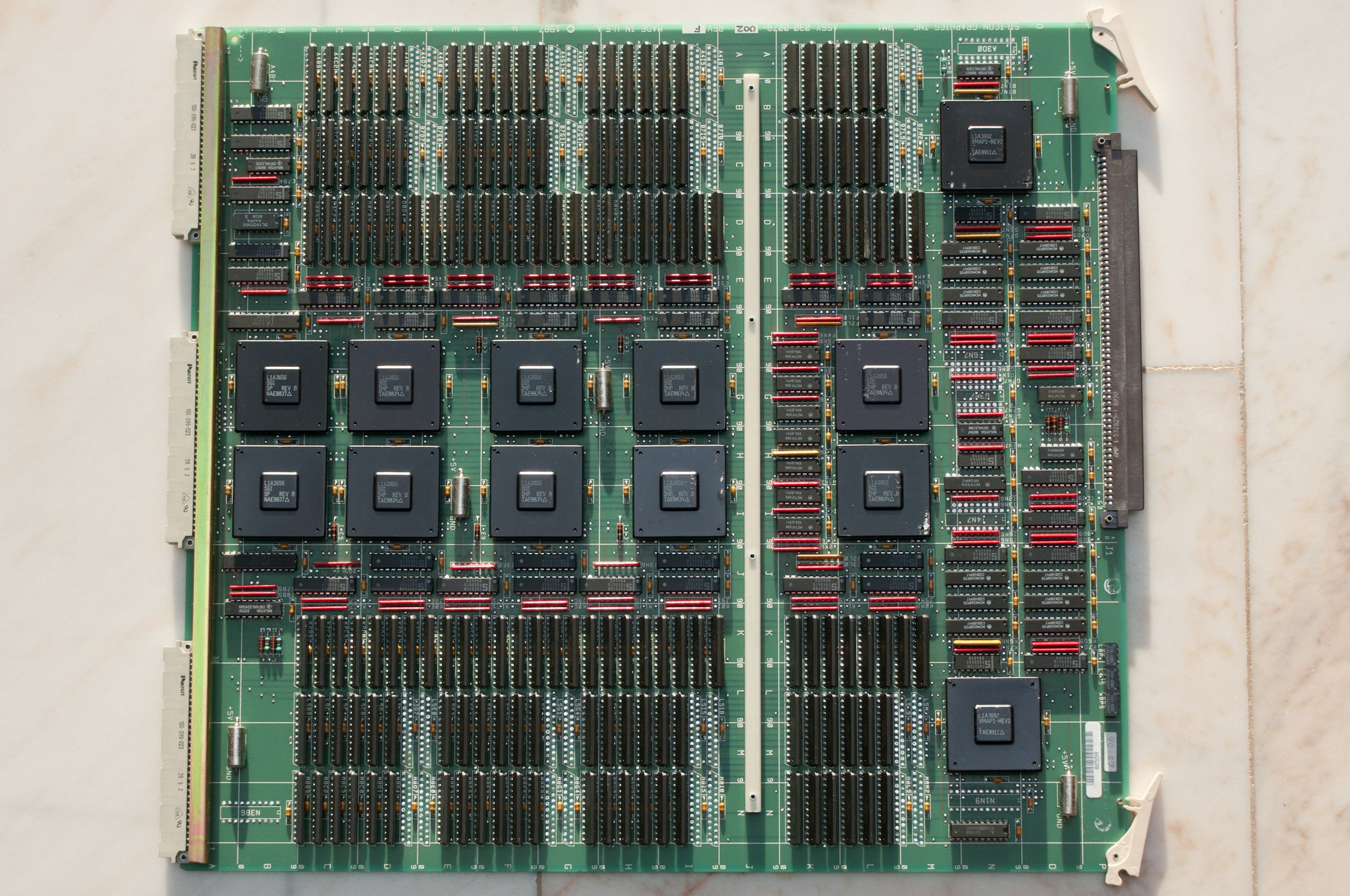
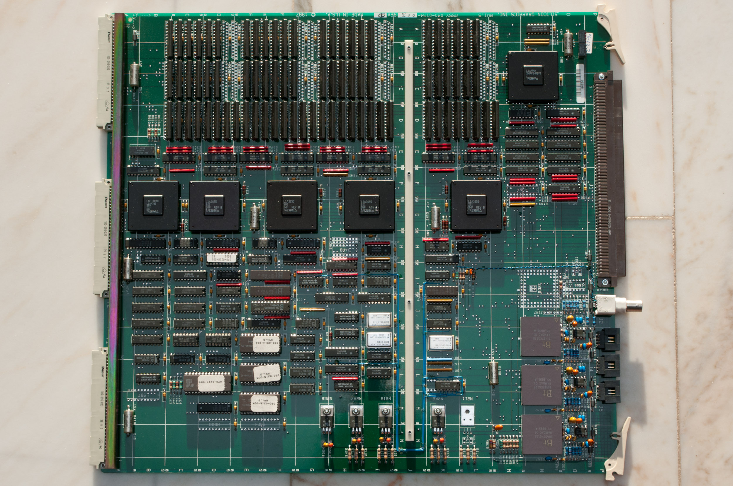
VGX Graphics
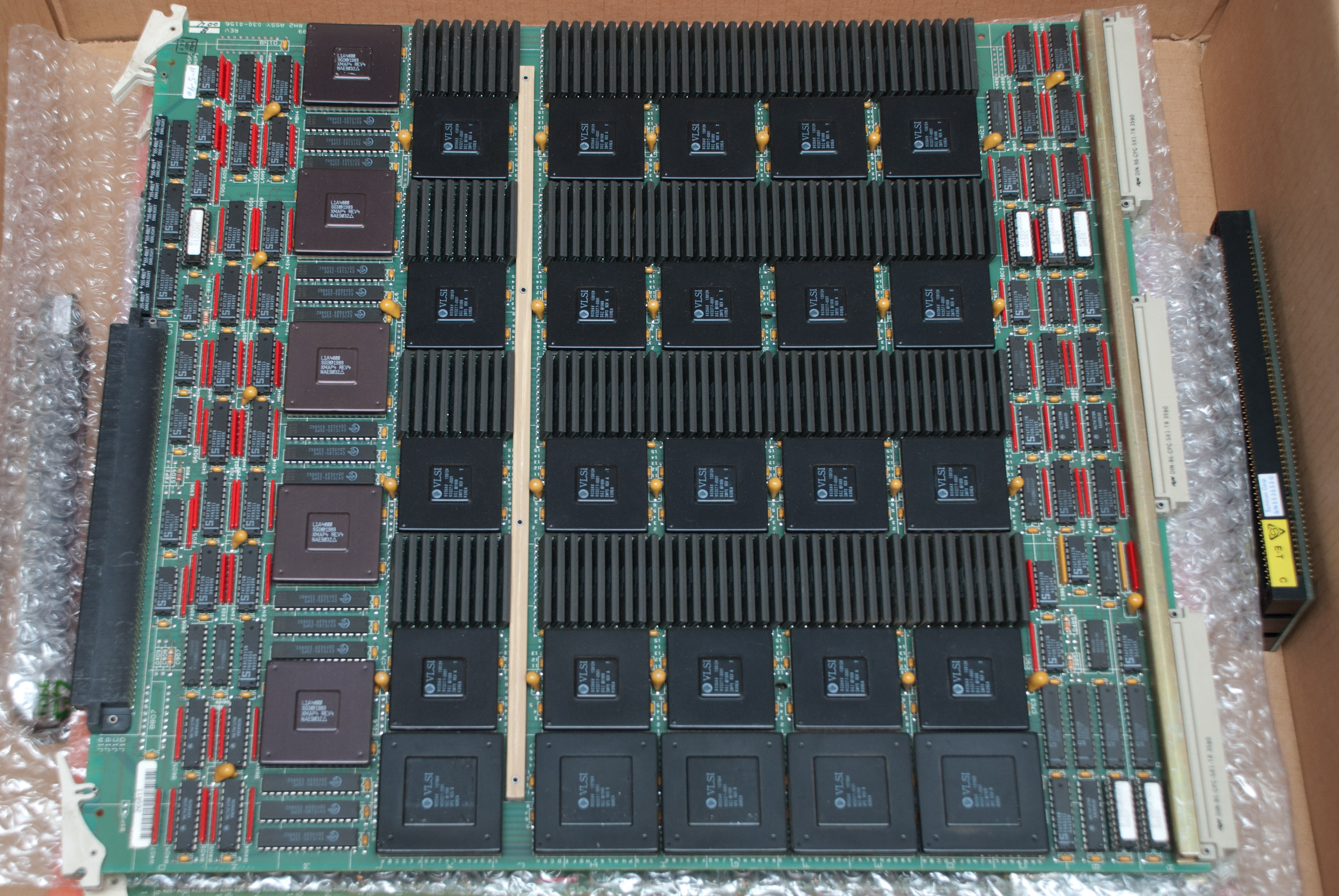
VGX Graphics Manager (GM3).
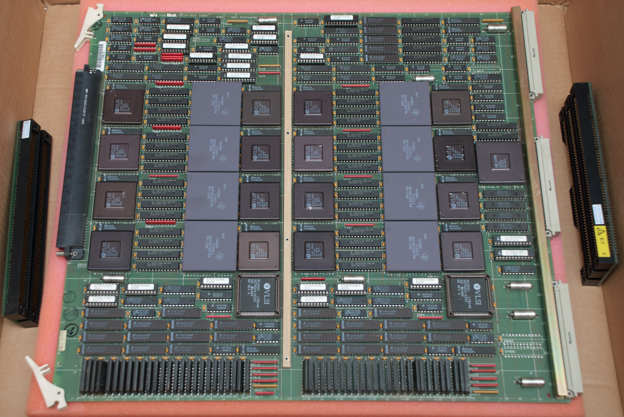
VGX Geometry Engine (GE6).
VGX Raster Manager (RM2).
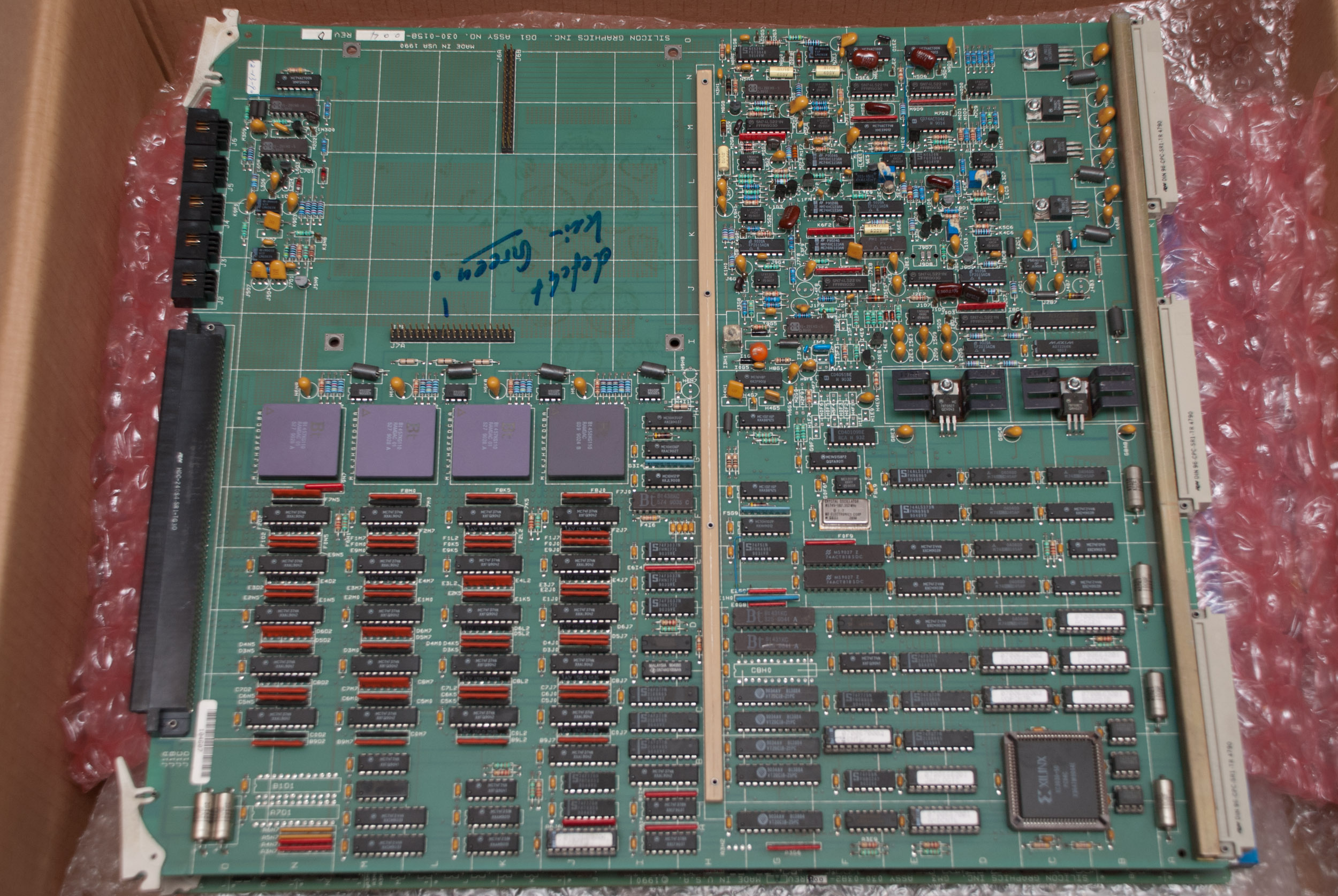
VGX Display Generator (DG1)
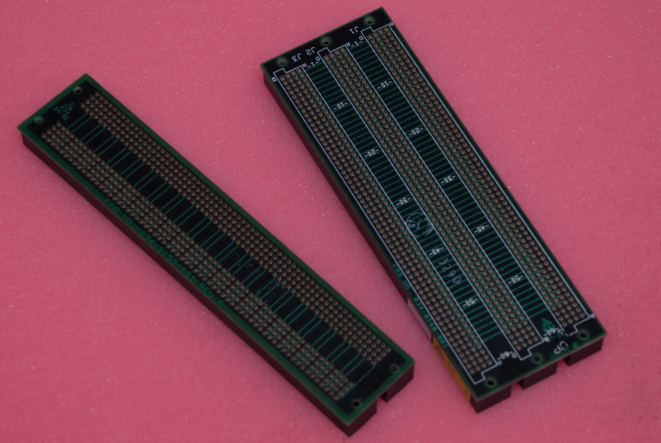
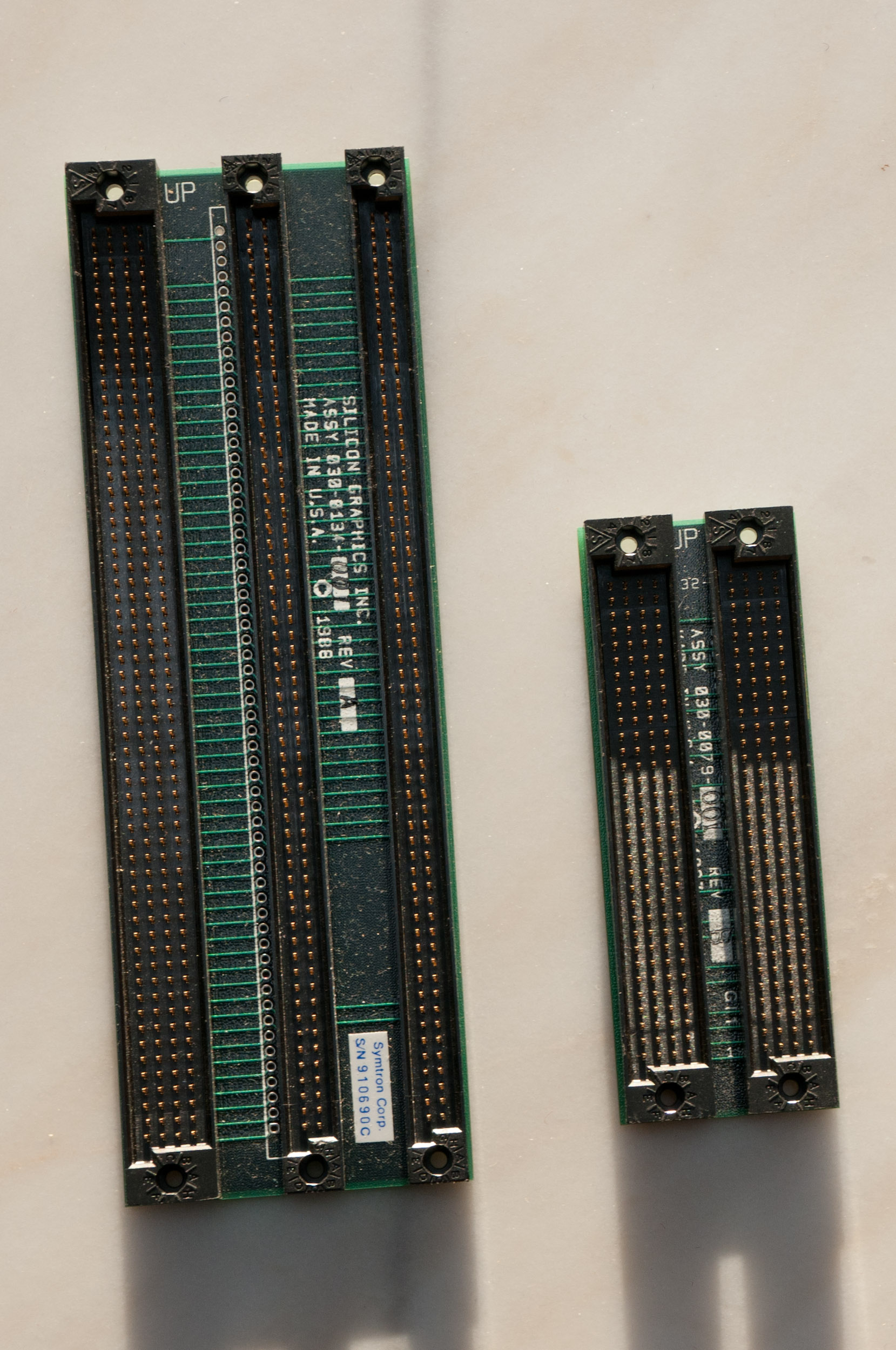
VGX card edge connector.
Reality Engine Upgrade

Crimson Elan frontpanel.
Crimson Elan cardcage.
Crimson Reality Engine frontpanel.
Crimson Reality Engine cardcage.
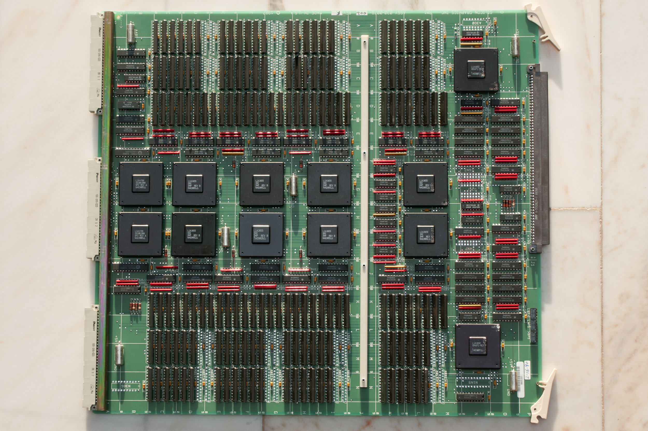
Reality Engine
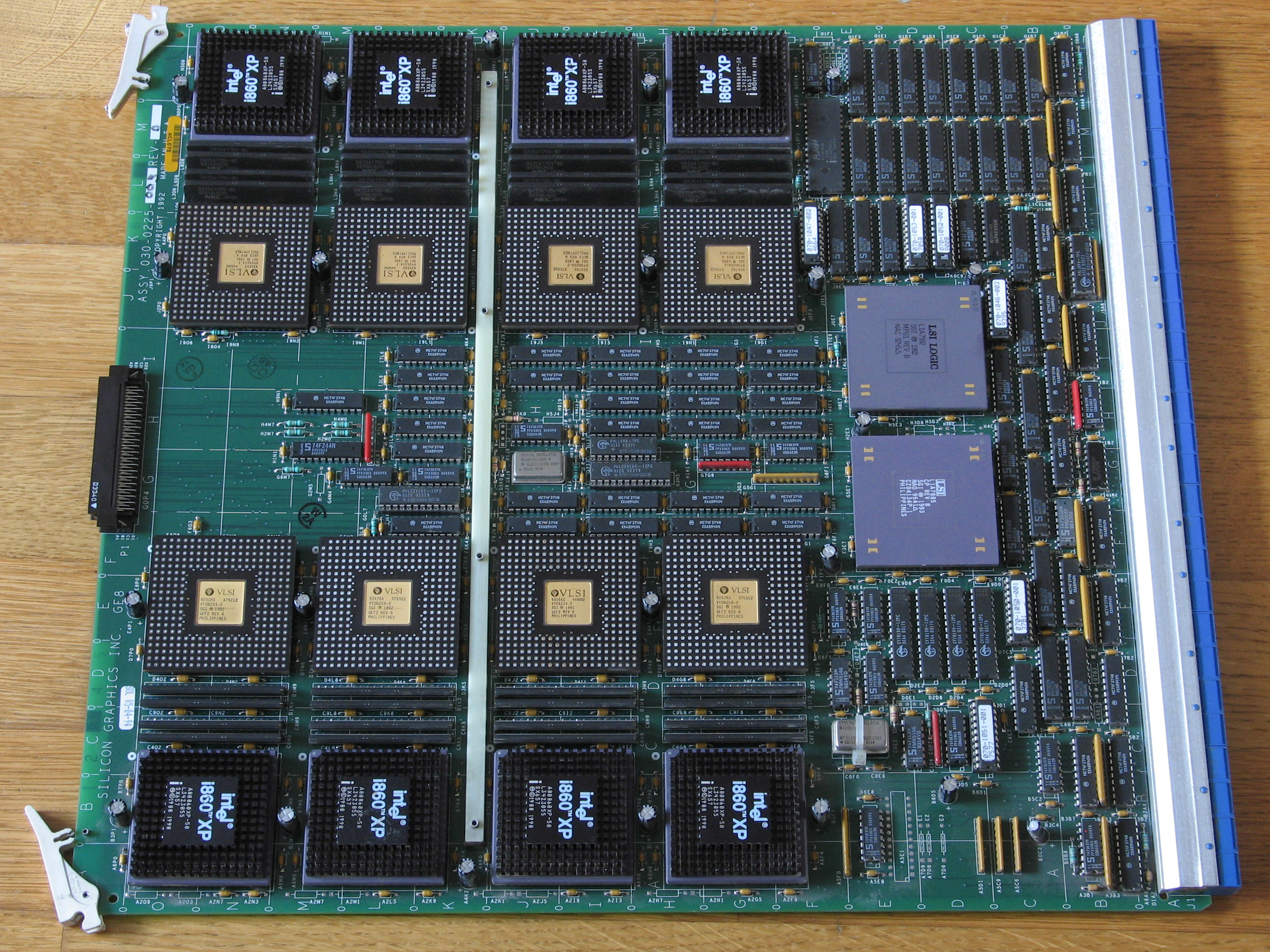
GE8 Geometry Engine (Reality Engine).
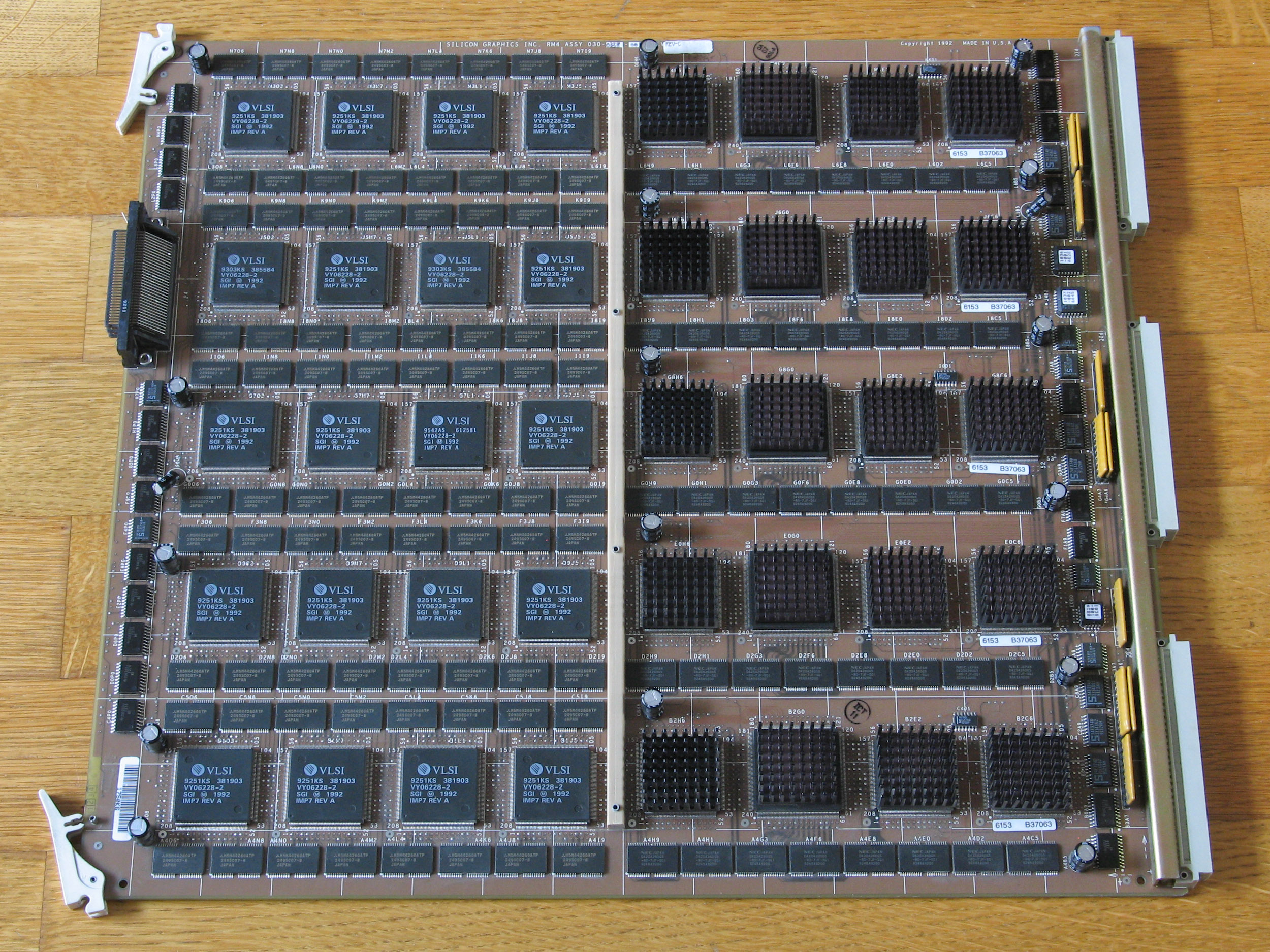
RM4T Raster Manager terminated (Reality Engine).

DG2 Display Generator (Reality Engine).
Links
Articles
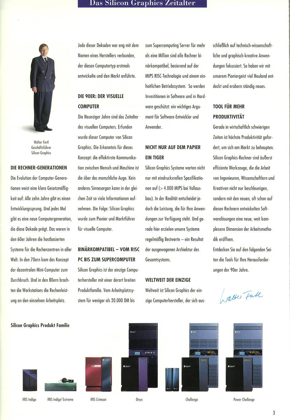
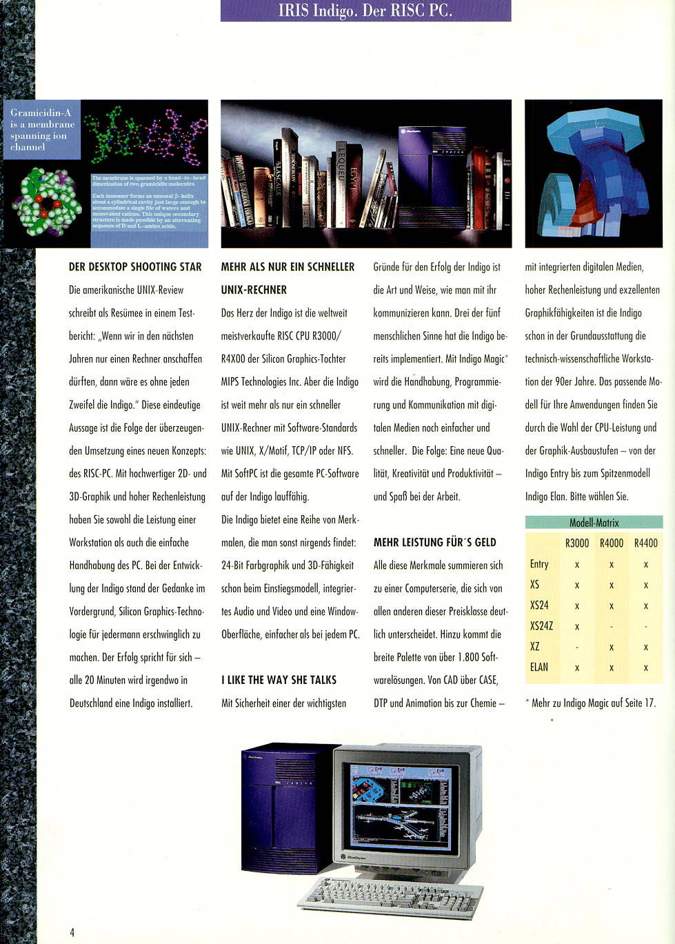
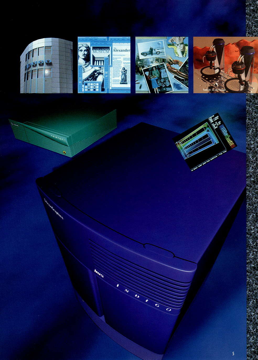
- An SGI catalogoue from approx. 1994 featuring pictures (DIN A4 fullsize) and short german descriptions of Indigo, Indigo 2, Crimson, Onyx, Challenge and Power Challenge: Page 1, 3, 4, 5, 6, 7, 8, 9, 10, 11, 12, 13, 14, 15 (numbers refer to the original page number, not the filename; Scan by Ganjatron)
Technical Papers
- Crimson Info and Technical highlights as posted on 29 January 1992 [local]
Websites
- Futuretech: Crimson - Ian Maplesons Crimson page
- Big Old Nasty SGI Page - lots of pictures, good information on the old and big systems
- Crimson/PowerSeries/Onyx RealityEngine/RealityEngine2 Info [local mirror]