Graphics
Clover 2
Introduction
General
The "Clover 2" graphics option has been introduced during the days of the Professional Iris systems. It has been made available for for the PowerSeries systems after their introduction. Because of the relation between these and the Crimson "Clover 2" graphics was also available there.
The series of "Clover 2" graphics options thus can be separated into two different sub families: GT, the oritinal graphics option for the Professional Iris and GTX, the version for Crimson/PowerSeries. Both the first series GT as well as the second series GTX graphics are available in a lower cost version that does not include hardware support for alpha bitplanes. These are referred to as GTB and GTXB.
Features
The following excerpt on GT graphics has been posted to Usenet by John Dunbar on 22 July 1995. The actual text seems to be taken out of a marketing brochure from the late 80s:
The IRIS GT is a set of five PCBs that upgrade the graphics performance and
functionality of Silicon Graphics IRIS 4D Series Superworkstations. The IRIS GT
combines the latest advances in silicon technology with a new, proprietary
frame buffer architecture that incorporates seven new VLSI graphics processors
designed by Silicon Graphics.

These graphics processors provide hardware support for advanced lighting
models, smooth shading, antialiased lines, pan and zoom of images, and a
variety of other graphics features. The architecture provides 16.7 million
colors in double buffered RGB mode, and 4096 colors from a 16.7 million color
palette in color index mode. A high resolution 24-bit Z-buffer supports
accurate hidden surface removal. The IRIS GT represents a major breakthrough in
display system quality and graphics performance.

The standard configuration includes:

1280 x 1024 x 48 bitplanes display memory for color

1280 x 1024 x 4 bitplanes display memory for overlays, underlays, and
user-enhancement functions

1280 x 1024 x 4 bitplanes display memory dedicated for system use (not
user-accessible)

24-bit Z-buffer for hidden surface removal

Hardware support for fast Gouraud shading

Support of multimode graphics in a windowing environment.

Hardware support for diffuse, ambient, and specular lighting models using
multiple colored local and  infinite light sources

Hardware support for arbitrarily shaped windows

Hardware support for antialiased lines
These graphics language for this systems is IRIS GL, there is no OpenGL support in hardware. The last IRIX version to support GTX/GTXB is IRIX 5.3.
Technology
Architecture
The Clover 2 graphics subsystem is attached to the host workstation via a 64bit wide proprietary bus. The graphics hardware itself is divided into these four parts (ordered as data passes through them):
- Geometry subsystem
- Scan conversion subsystem
- Raster subsystem
- Display subsystem
This description is based on Kurt Akeley and Tom Jermoluks description of the hardware (see reference below).
Geometry subsystem
The geometry subsystem transforms data from object-space coordinates to screen-space coordinates (floating-point operation). The main parts which form a single pipeline of this system are:
- 1 conversion / FIFO module
- 5 floating point processors (Geometry Engines)
A 512 word FIFO is the beginning of the pipeline and buffers data sent to the graphics subsystem. It interrupts the data stream on it's own when a high water mark is passed and allows further data when a low water mark is reached (i.e. when more data has been processed by the pipeline). The conversion module accepts all coordinets into 32-bit IEEE floating point format.
All five Geometry Engines are identical processors (Weitek 3332) capable of 20 Mflops. Each of them is used only for a specific task:
- Matrix and normal transformation.
- Lighting calculations.
- Clip testing.
- Perspective division. Clipping.
- Viewport transformation. Depthcue calculations.
The geometry subsystem then feeds the data into the Scan-Conversion subsystem.
Scan conversion subsystem
The scan conversion subsystem converts vertexes to points, lines and polygons. It generates the appropriate fill instructions and interpolates color and depth data across these elements. Three processors are used to do this kind of transformation:
- 1 Polygon processor which sorts the vertexes and decomposes them to trapezoids.
- 1 Edge processor which analyzes the top and bottom edges of the trapezoids and thus determines the top and bottom coordinates of each span.
- 5 Span processors each of which manages every fifth column in the framebuffer.
Raster subsystem
The raster subsystem maintains the 1280*1024 frame buffer of 96-bit pixels:
- 32 bit image memory (8bit RGBA)
- 32 bit image memory (8bit RGBA)
- 24 bit Z-buffer
- 4bit Window ID buffer
- 4bit Underlay/Overlay buffer
The raster subsystem executes pixel functions as replace, depth conditional replace (Z buffered) or blend. It contains 20 Image Engines each of which manages 1/20th of the frame buffer memory. Groups of 4 of these are driven by one span processor so that the frame buffer is tiled in a 5-wide and 4-high pattern:
  [SP1]   [SP2]   [SP3]   [SP4]   [SP5]
   IE1     IE2     IE3     IE4     IE5
   IE6     IE7     IE8     IE9     IE10
   IE11    IE12    IE13    IE14    IE15
   IE16    IE17    IE18    IE19    IE20
The bitplane memory is divided into 5 banks which are arranged as follows (the system uses 8bit RGBA - double buffered):
                   color      alpha     window id     overlay     depth
GT/GTX              48         16           4            4         24
GTB/GTXB            48          -           4            4          0
Boards
GT Boardset
The following boards belong to a this boardset:
- GM1
- Graphics Manager Board, equipped with a Motorola MC68020RC16B processor (for GT/GTB). It is equipped with a host interface for Professional Iris systems (only).
- GE4
- Geometry Engine Board, equipped with 5 Weitek 3332 processors (20 MFLOPS each) that act as Geometry Engines. Unlike later systems each of the GEs is performing a different task on Clover 2 class graphics options.
- RM1
- Raster Manager Board - a GT graphics boardset requires two Raster Manager Boards.
- RV1
- Raster Video Board with support for Alpha-planes.
GTB Boardset
The following boards belong to a this boardset:
- GM1
- Graphics Manager Board, equipped with a Motorola MC68020RC16B processor (for GT/GTB). It is equipped with a host interface for Professional Iris systems (only).
- GE4
- Geometry Engine Board, equipped with 5 Weitek 3332 processors (20 MFLOPS each) that act as Geometry Engines. Unlike later systems each of the GEs is performing a different task on Clover 2 class graphics options.
- RM1-NA
- Raster Manager Board - a GTB graphics boardset requires two Raster Manager Boards.
- RV1-NA
- Raster Video Board without support for Alpha-planes.
GTX Boardset
The following boards belong to a this boardset:
- GM2
- Graphics Manager Board, equipped with a Motorola MC68020RC16B processor (for GTX/GTXB). The GM2 has a host interface for PowerSeries machines (only).
- GE4
- Geometry Engine Board, equipped with 5 Weitek 3332 processors (20 MFLOPS each) that act as Geometry Engines. Unlike later systems each of the GEs is performing a different task on Clover 2 class graphics options.
- RM1.5
- Raster Manager Board - a GTX graphics boardset requires two Raster Manager Boards.
- RV1.5
- Raster Video Board with support for Alpha-planes.
GTXB Boardset
The following boards belong to a this boardset:- GM2
- Graphics Manager Board, equipped with a Motorola MC68020RC16B processor (for GTX/GTXB). The GM2 has a host interface for PowerSeries machines (only).
- GE4
- Geometry Engine Board, equipped with 5 Weitek 3332 processors (20 MFLOPS each) that act as Geometry Engines. Unlike later systems each of the GEs is performing a different task on Clover 2 class graphics options.
- RM1.5-NA
- Raster Manager Board - a GTXB graphics boardset requires two Raster Manager Boards.
- RV1.5-NA
- Raster Video Board without support for Alpha-planes for GTXB.
There is also a RV2 board which is a single board replacement for RM1.5-NA and RV1.5-NA. It was only available for the non-alpha GTXB version of the Clover graphics option.
Setup
GT/GTB
The following shows the configuration for a 12 slot TwinTower (Professional Iris) system:
| 08 | GFX | GE4 | GE4 and GM1 are bridged using a card edge connector board |
| 09 | GFX | GM1 | |
| 10 | GFX | RM1 | RM1 and RV1 are bridged using a card edge connector board |
| 11 | GFX | RV1 | |
| 12 | GFX | RM1 |
GTX/GTXB
The following table shows the configuration for a 15 slot TwinTower (PowerSeries) system:
| 10 | GFX | GM2 | GM2 and GE 4 are bridged using a card edge connector board |
| 11 | GFX | GE4 | |
| 12 | GFX | RM1 | RM1 and RV1 are bridged using a card edge connector board |
| 13 | GFX | RM1 | |
| 14 | GFX | RV1 | |
| 15 | GFX | empty |
The following table shows the configuration for a SingleTower (PowerSeries) system:
| 09 | GFX | GM2 | GM2 and GE 4 are bridged using a card edge connector board |
| 10 | GFX | GE4 | |
| 11 | GFX | RM1 | RM1 and RV1 are bridged using a card edge connector board |
| 12 | GFX | RM1 | |
| 13 | GFX | RV1 | |
| 14 | GFX | empty |
The following table shows the configuration for a Rack (PowerSeries) system:
| 14 | GFX | GM2 | GM2 and GE 4 are bridged using a card edge connector board |
| 15 | GFX | GE4 | |
| 16 | GFX | RM1 | RM1 and RV1 are bridged using a card edge connector board |
| 17 | GFX | RM1 | |
| 18 | GFX | RV1 | |
| 19 | GFX | empty |
Pictures
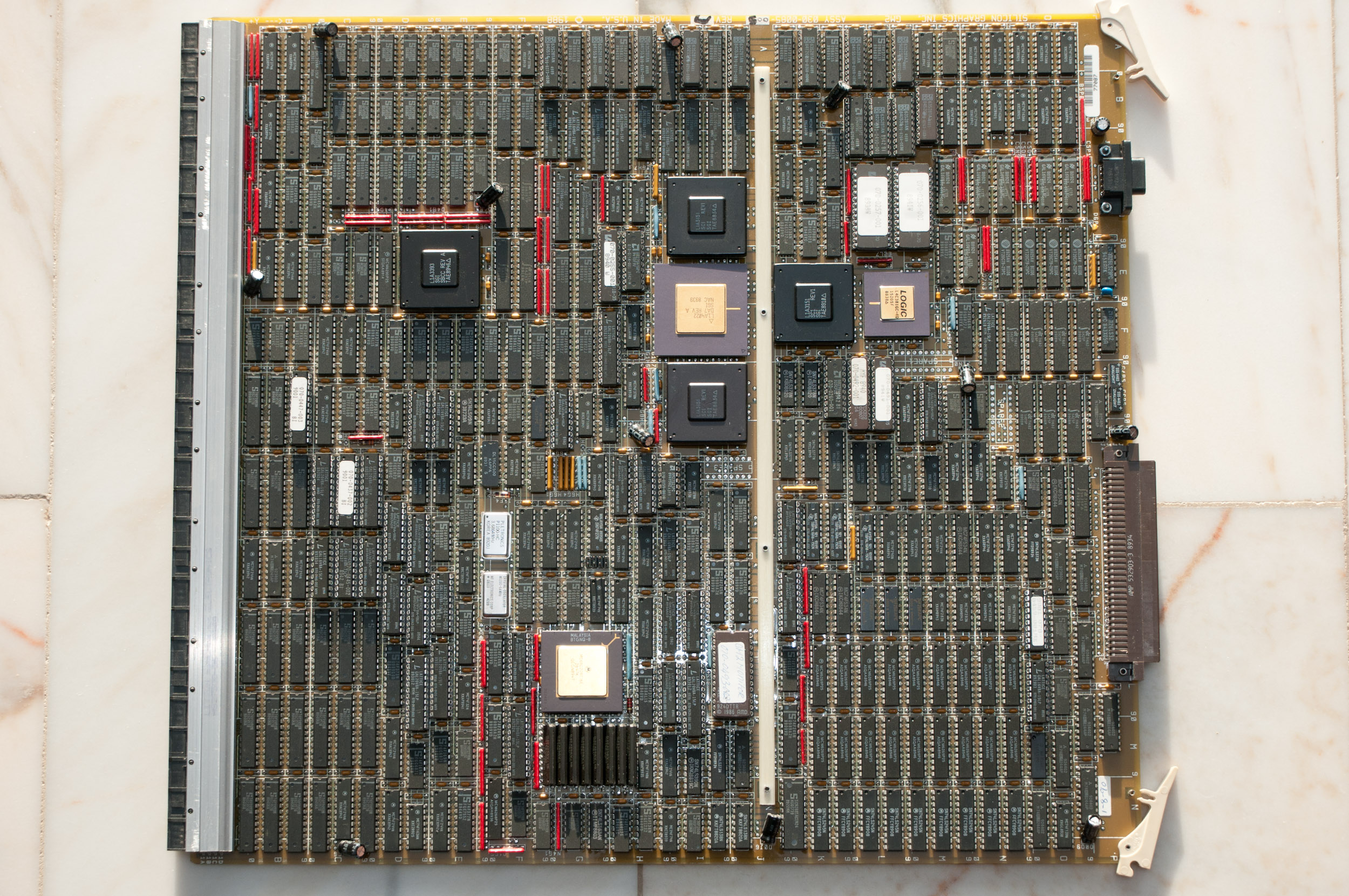
GTX GM2 Graphics Manager.
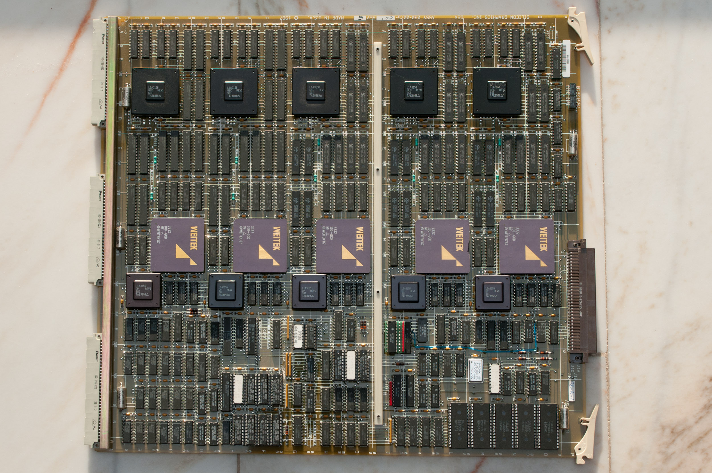
GTX GE4 Geometry Engine.
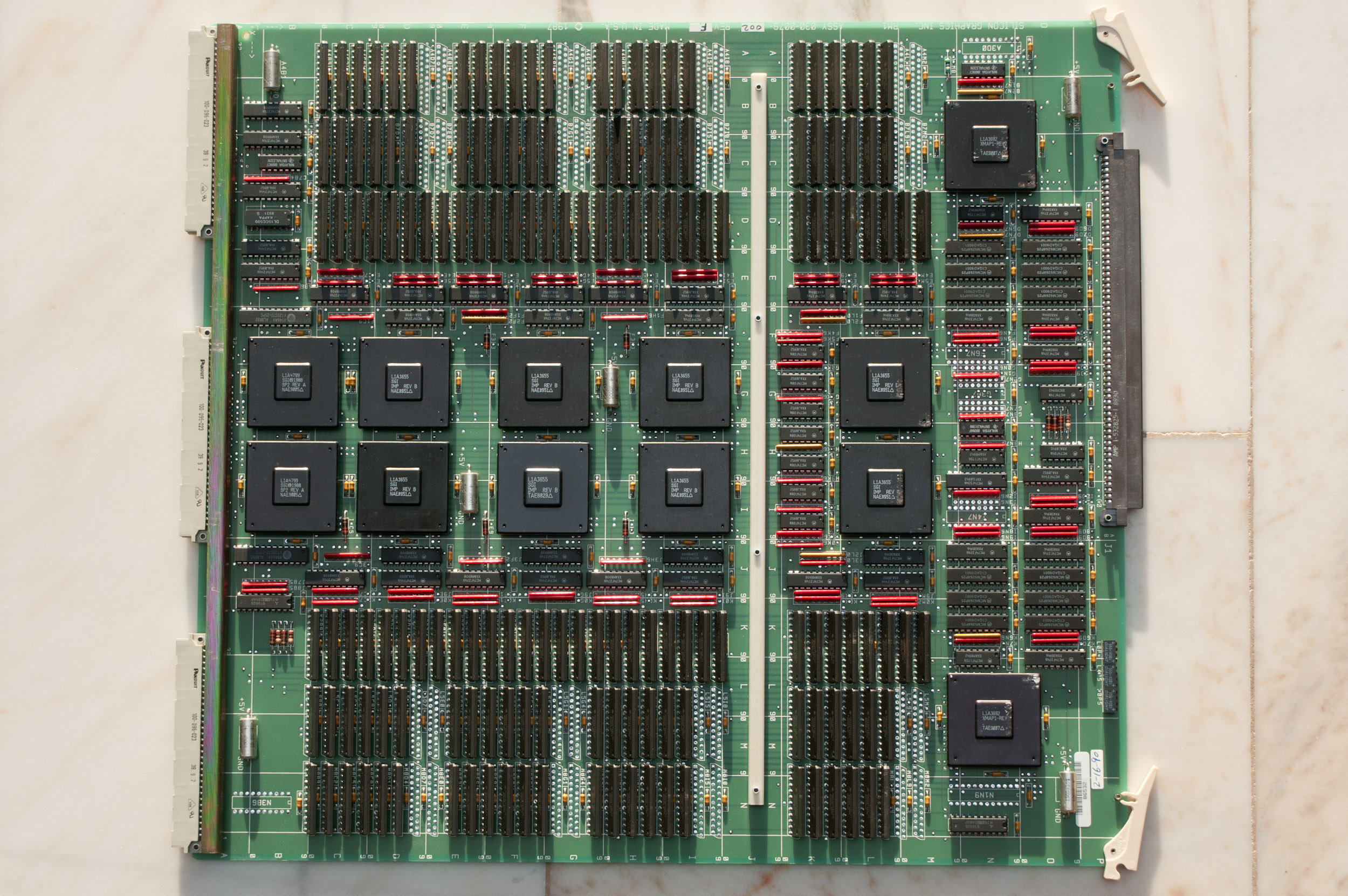
GTX RM1 Raster Manager.
GTX RM1 Raster Manager.
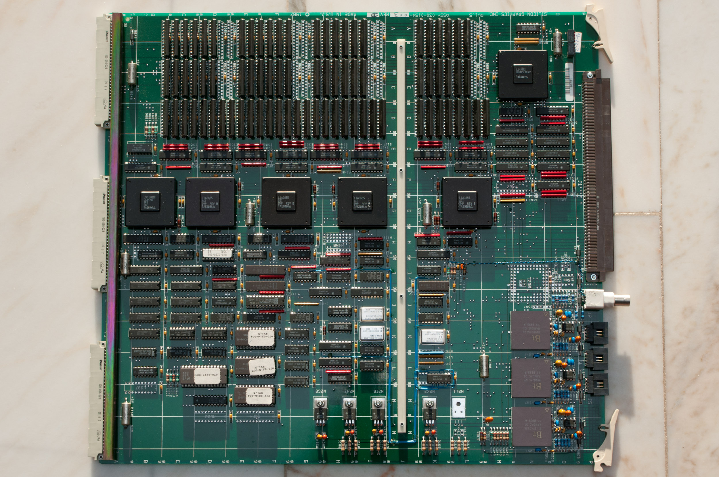
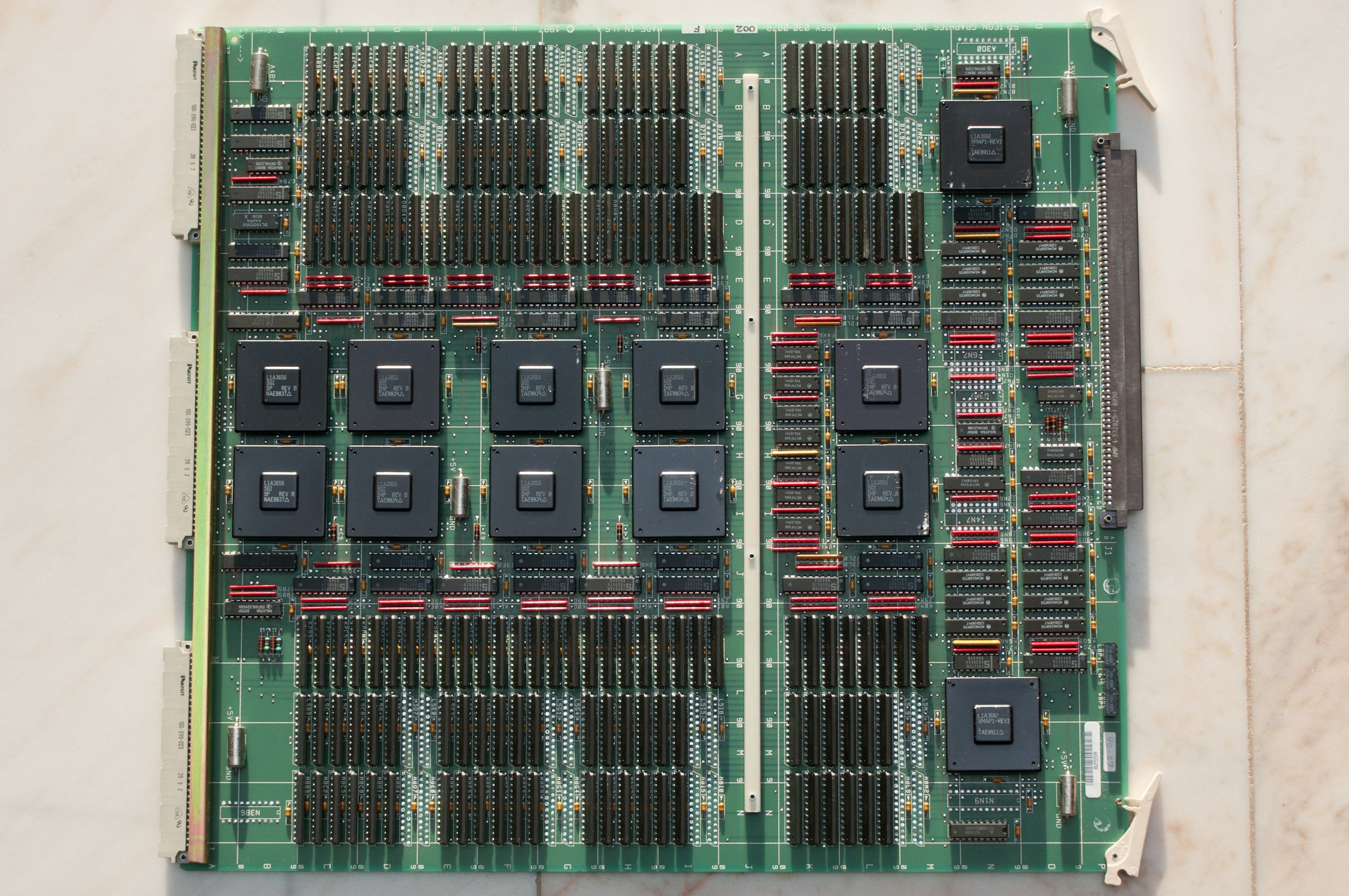
GTX RV1.5 Raster Video.
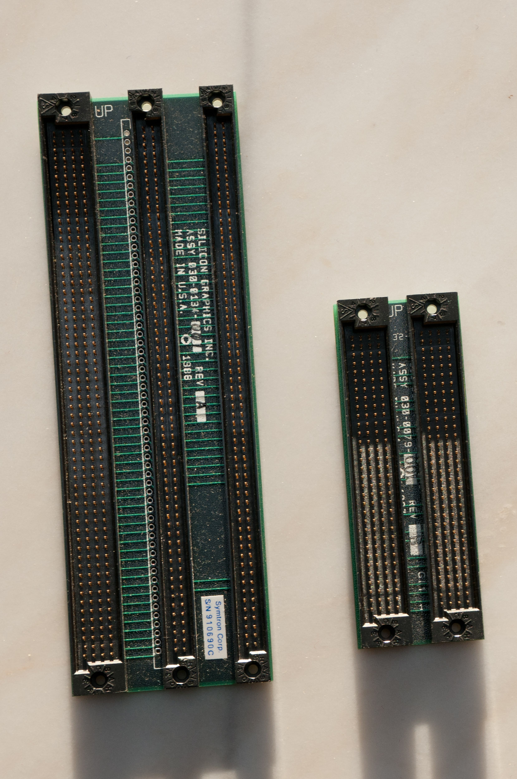
GTX connector.
Links
Websites
- This Old SGI FAQ [local mirror]
Articles
- High-Performance Polygon Rendering
Kurt Akeley and Tom Jermoluk [Published by ACM in 1988]