Graphics
Reality Engine
Introduction
General
The RealityEngine (code name "Venice") was the state of the art graphics option for the Crimson and the late models of the PowerSeries. In a Skywriter chassis two complete RealityEngine Pipelines can be used (see also "Starpuft: VGXT").
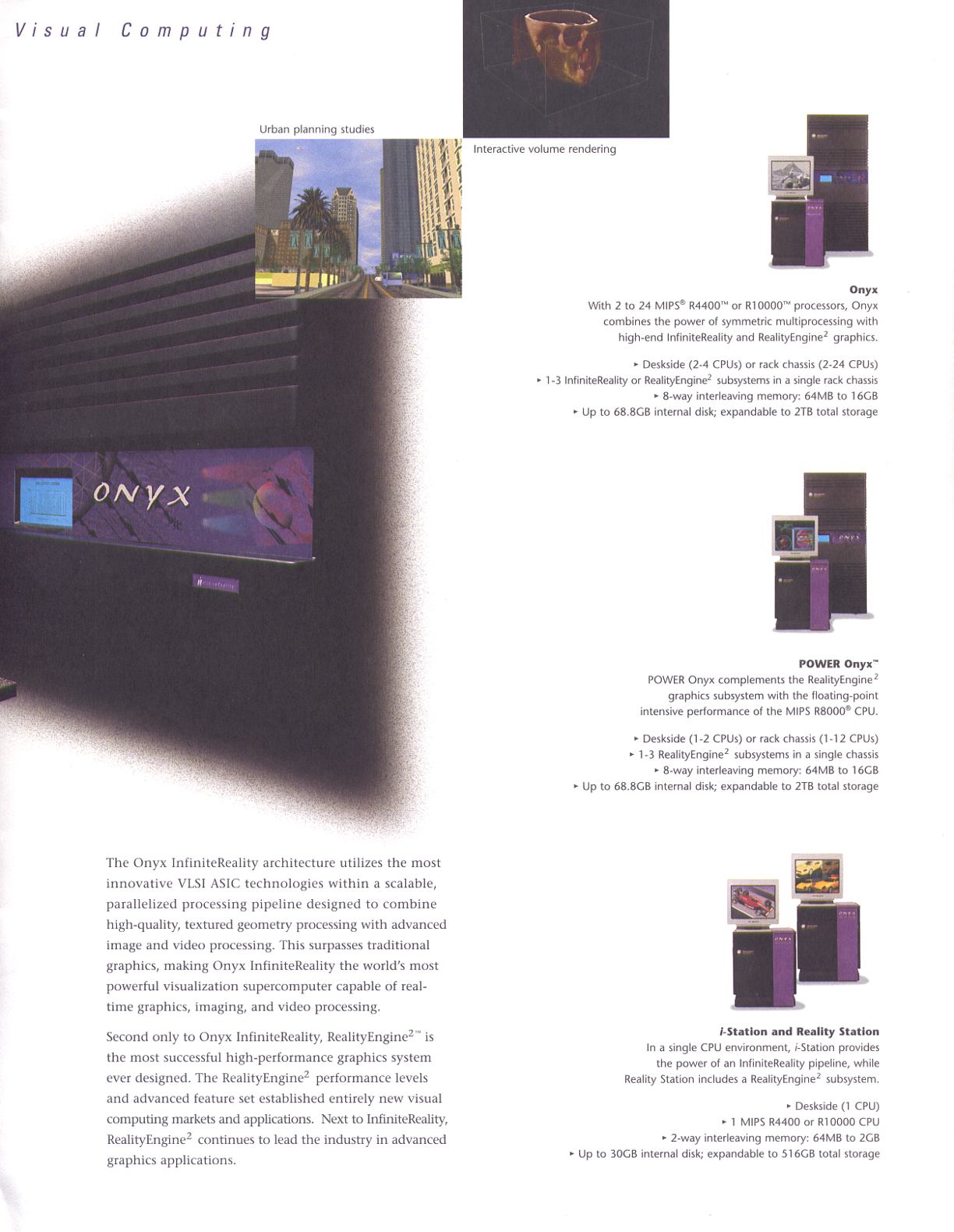
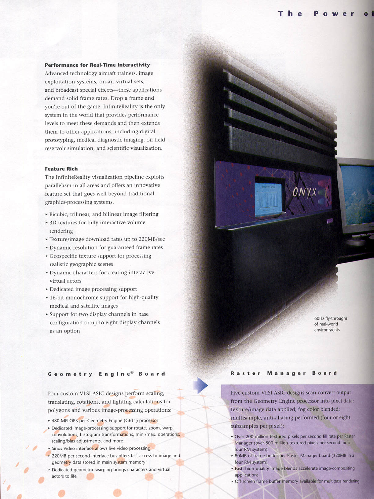
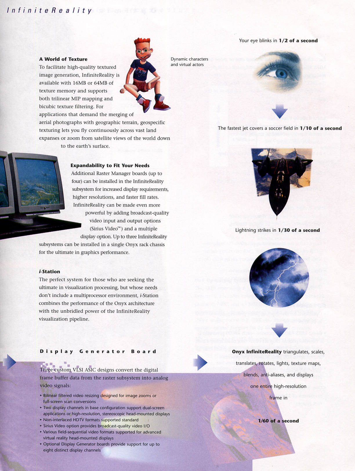
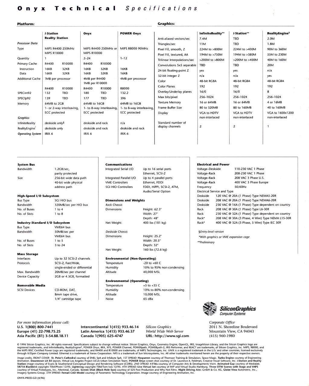
The more advanced RealityEngine 2 was introduced for the Onyx graphics supercomputers in 1993 as well as it's smaller brother VTX. Both offer real-time, multisample anti-aliasing, advanced stereo, 96-bit color, volume rendering, and a 32-bit Z-buffer.
Rackmount systems can include more than one RealityEngine 2 pipelines. In addition to that the TKO "Triple Keyboard Option" setup allows a multi pipline system to run up to three independent displays with input devices.
To compare RealityEngine, RealityEngine 2 and VTX use the following chart, the information is taken from ancient marketing brochures (where available):
Graphics:                            RealityEngine       VTX                 RealityEngine2

Anti-aliased vectors/sec:            n/a                 1.0M                2.0M
Triangle Meshes/sec:                 1.1M                1.1M                1.6M
T-Mesh Gouraud Z, lit:               n/a                 813K                1.0M
T-Mesh Textured:                     n/a                 600K                988K
Quad Strips, Gouraud, Z:             n/a                 350K                530K
Pixel Fill, smooth, Z:               n/a                 90M                 90-360M
Pixel Fill, textured, aa:            n/a                 n/a                 n/a
55-230M 24-bit Z:                    n/a                 yes                 yes
32-bit Z:                            n/a                 yes                 yes
Color:                               n/a                 48-bit RGB          48-bit RGBA
Color Planes:                        n/a                 192                 192
Overlay/Underlay planes:             n/a                 8                   8
Max bits/pixel:                      n/a                 256                 256-1024
Texture Memory:                      n/a                 4MB                 4 or 16MB
Frame Buffer Size:                   n/a                 40MB                40 to 160MB
Display:                             n/a                 VGA to              VGA to
                                     n/a                 1280x1024           HDTV32-bit
32 Pixel Read/Write:                 n/a                 21.1M/26.8M         28.3M/29.1M
Boards
Reality Engine
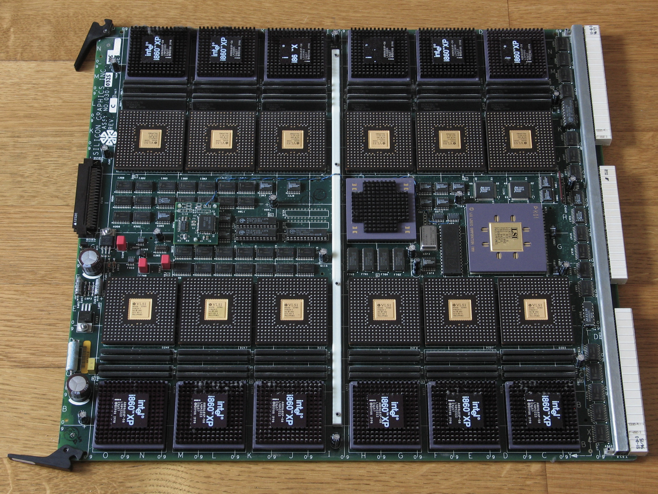
- GE8 Geometry Engine
- The GE8 board contains the actual Geometry Engine with 8 Intel i860XP processors as well as the interface to the host system.
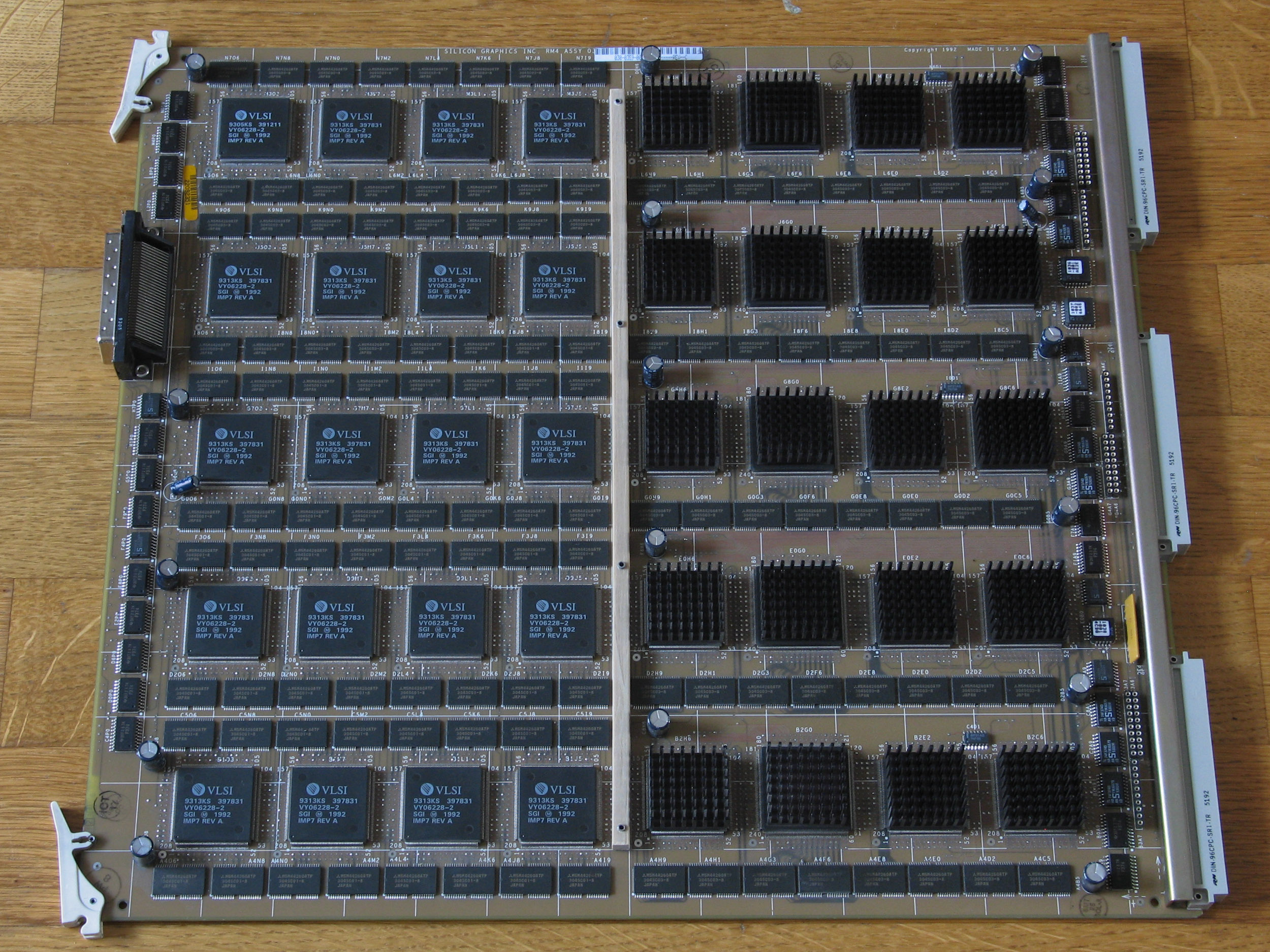
- RM4 Raster Manager
- Up to 4 RM4 boards are supported depending on chassis type. The last RM4 board in the line (rightmost one) needs to be terminated (RM4T). Termination is required on the RM side of the graphics pipeline and is done by adding appropriate resistors into the sockets on the RM4 board. This is required on Crimson and PowerSeries only.
- DG2 Display Generator
- The Display Generator creates an analog output for display.
Reality Engine 2 and VTX
- GE10 Geometry Engine
- The GE10 board contains the actual Geometry Engine with 12 Intel i860XP processors on RealityEngine2 or 6 Intel i860XP processors on VTX systems as well as the interface to the host system.
- RM4 or RM5 Raster Manager
- With RealityEngine 2 the systems support 1, 2 or 4 RMs, with VTX only 1. Systems with RM4s have 4MB texture memory, the ones with RM5s 16 MB regardless of the amount of RM boards installed. Additional RM boards enhance the amount of available frame buffer memory (40 MB each). Termination on the RM boards is not required for Onyx/VTX or Onyx/RealityEngine2 setups, it has been moved into the backplane.
- DG2 Display Generator
- The Display Generator that creates an analog output for display is the same for RealityEngine 2 and VTX.
RM4 vs. RM4T
The main difference between the RM4T boards that are required in the last Reality Engine slot in Crimson/PowerSeries systems and the general RM4 boards suitable for any other space in Reality Engine or Reality Engine 2 setups are the jumper blocks added in the otherwise empty spaces near the backplane connection.
There is one jumper pack soldered in place at a position between the two lower backplane connectors labelled A2A0 on any RM4 or RM4T board. Other than that there are three sockets for resistor packs lockated next to each VME style backplane connectores:
   B3A7  C3A7      G4A7            K6A7  L7A7
         C3A6      G4A6  H4A6            L7A6
There are no further jumpers or sockets on the RM4/RM4T board.
Setup
RealityEngine
The following shows the configuration for a 15 slot TwinTower (PowerSeries) system:
| 10 | GFX | GE8 | |
| 11 | GFX | DG2 | Bridged using a carde edge connector. |
| 12 | GFX | ||
| 13 | GFX | ||
| 14 | GFX | RM4 (optional) | |
| 15 | GFX | RM4T |
The following shows the configuration for a SingleTower (PowerSeries) system:
| 9 | GFX | GE8 | |
| 10 | GFX | DG2 | Bridged using a carde edge connector. |
| 10 | GFX | ||
| 12 | GFX | ||
| 13 | GFX | RM4 (optional) | |
| 14 | GFX | RM4T |
The following shows the configuration for a Rack (PowerSeries) system:
| 14 | GFX | GE8 | |
| 15 | GFX | DG2 | Bridged using a carde edge connector. |
| 16 | GFX | RM4 (optional) | |
| 17 | GFX | RM4 (optional) | |
| 18 | GFX | RM4 (optional) | |
| 19 | GFX | RM4T |
Note the use of an RM4T in the rightmost slot of the cardcage and see the notes above regarding RM4 in the RealityEngine context.
Simon Pigot reports on his RealityEngine page that it is possible to run RM5 boards in an RealityEngine environment, but if it works depends on the revisions of the other cards used in the RealityEngine boardset, namely GE8 and DG2.
VTX
The following shows the configuration for a SingleTower (Onyx) system:
| 8 | GFX | GE10 | |
| 9 | GFX | DG2 | Bridged using a carde edge connector. |
| 10 | GFX | ||
| 11 | GFX | ||
| 12 | GFX | ||
| 13 | GFX | RM4/5 |
RealityEngine 2
The following shows the configuration for a Deskside (Onyx) system:
| 8 | GFX | GE10 | |
| 9 | GFX | DG2 | Bridged using a carde edge connector. |
| 10 | GFX | RM4/5 (optional) | |
| 11 | GFX | RM4/5 (optional) | |
| 12 | GFX | RM4/5 (optional) | |
| 13 | GFX | RM4/5 |
The following shows the configuration for the second cardcage in a Rackmount (Onyx) system:
| 11 | GFX | GE10 | |
| 12 | GFX | DG2 | Bridged using a carde edge connector. |
| 13 | GFX | RM4/5 (optional) | |
| 14 | GFX | RM4/5 (optional) | |
| 15 | GFX | RM4/5 (optional) | |
| 16 | GFX | RM4/5 |
The following table shows the configuration for the third cardcage in a Rackmount (Onyx) system:
| 5 | GFX | GE10 | |
| 6 | GFX | DG2 | Bridged using a carde edge connector. |
| 7 | GFX | RM4/5 (optional) | |
| 8 | GFX | RM4/5 (optional) | |
| 9 | GFX | RM4/5 (optional) | |
| 10 | GFX | RM4/5 | |
| ... | |||
| 16 | GFX | GE10 | |
| 17 | GFX | DG2 | Bridged using a carde edge connector. |
| 18 | GFX | RM4/5 (optional) | |
| 19 | GFX | RM4/5 (optional) | |
| 20 | GFX | RM4/5 (optional) | |
| 21 | GFX | RM4/5 |
Pictures
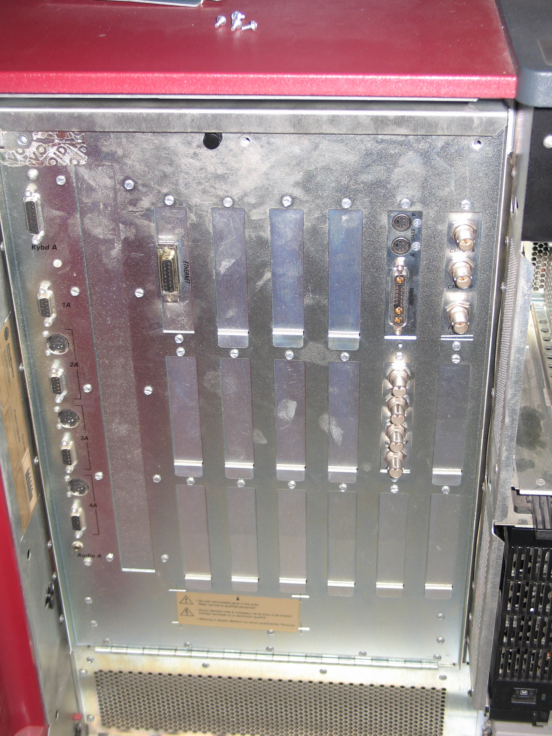
Crimson Reality Engine frontpanel.
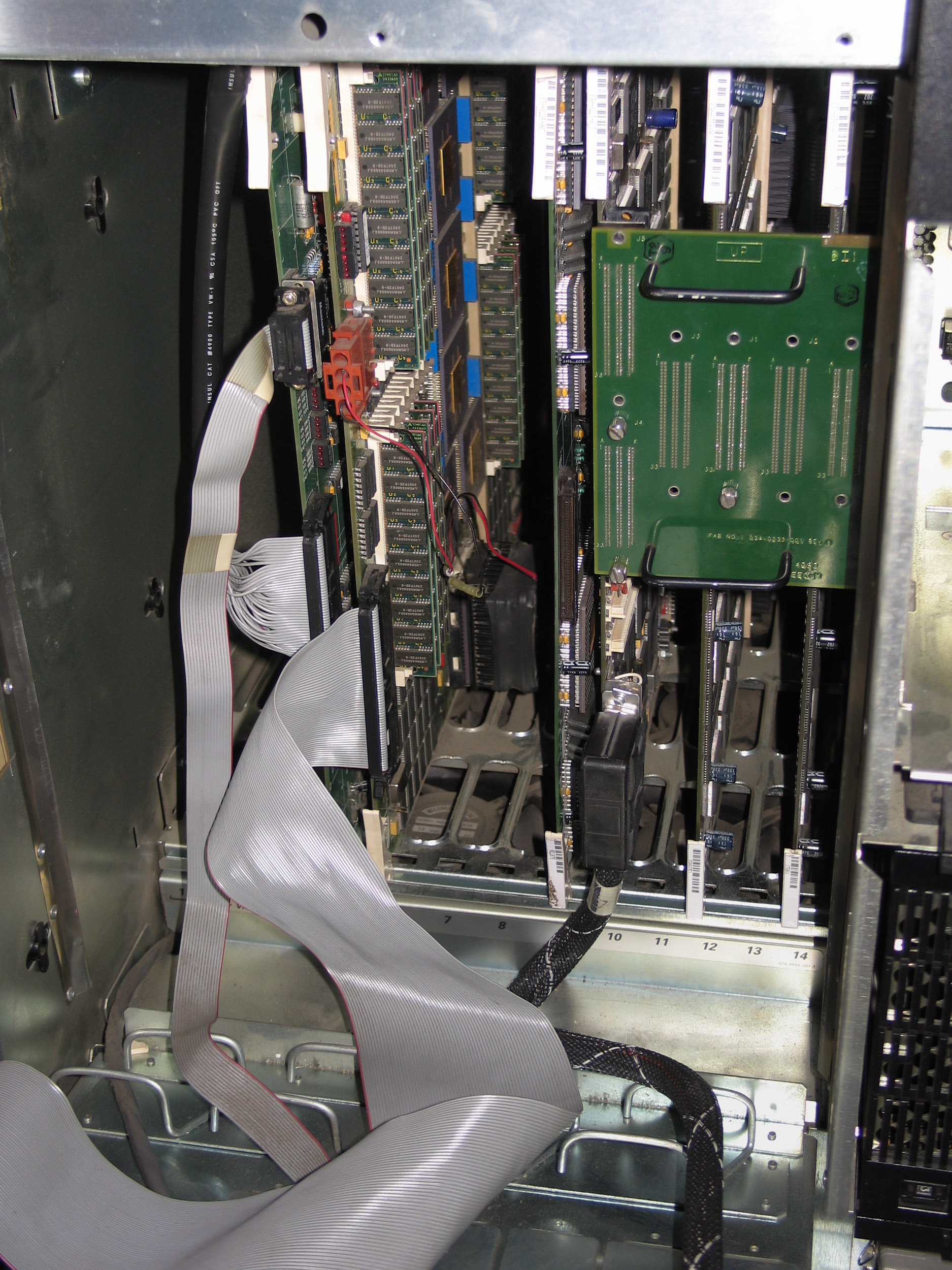
Crimson Reality Engine cardcage.
Reality Engine
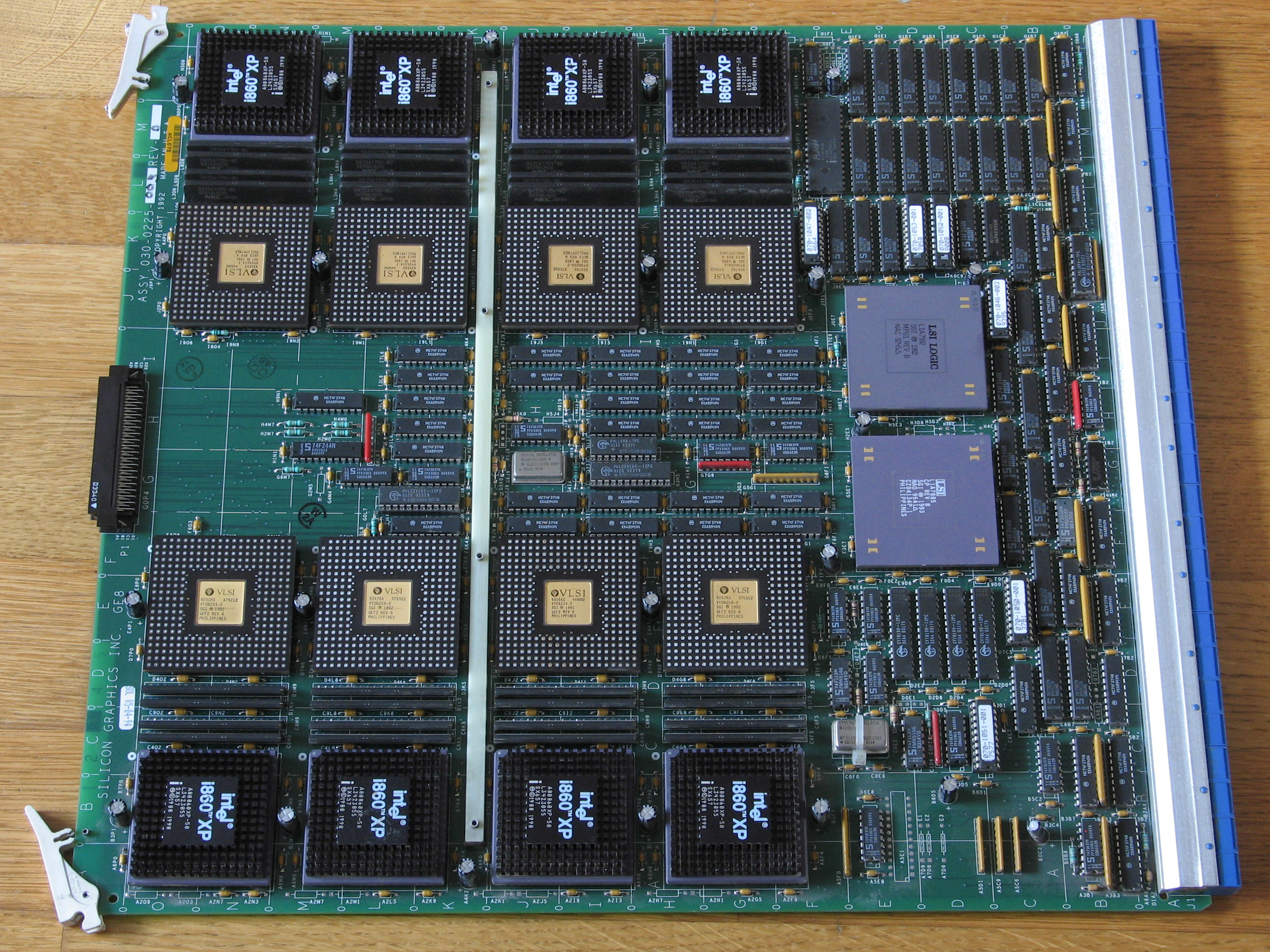
GE8 Geometry Engine (Reality Engine).
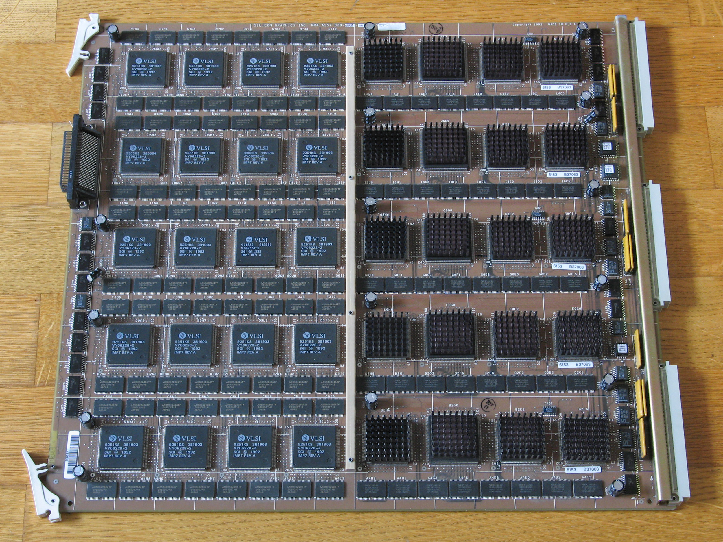
RM4T Raster Manager terminated (Reality Engine).

DG2 Display Generator (Reality Engine).
Reality Engine 2
GE10 Geometry Engine (Reality Engine 2).
RM4 Raster Manager (Reality Engine 2).
Links
Articles
- Kurt Akeley: RealityEngine Graphics, (c) 1993 Association for Computing Machinery
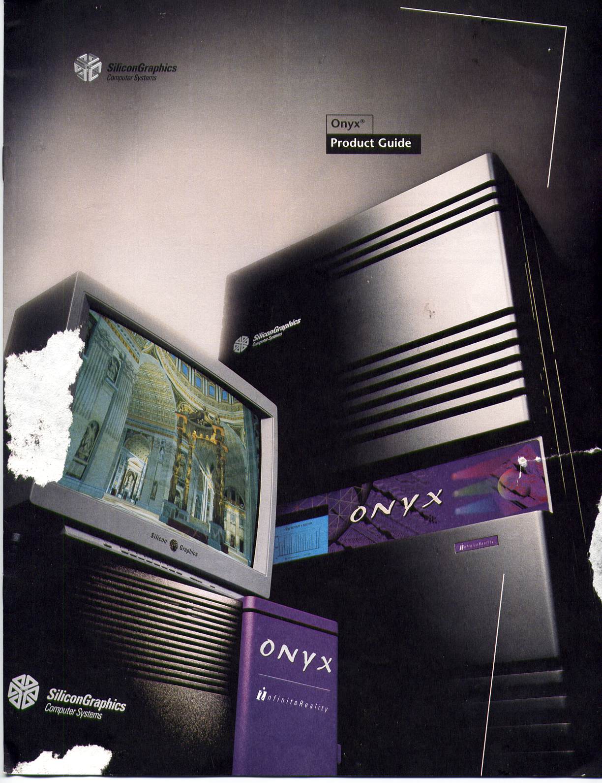
- An SGI product guide featuring the Onyx, Reality Engine and Infinite Reality graphics. Page: 1, 2, 3, 4, 5, 6, 7, 8, 9, 10, 11, 12
Websites
- Crimson/PowerSeries/Onyx RealityEngine/RealityEngine2 Info [local mirror]