R4400/150 IP17 and R4000/100 IP17
WARNING: If you use this info
below and blow/destroy/frazzle or otherwise maim your IP17 then don't blame
me - This info is not a guide to upgrading your R4000 IP17 - its just my
record of the visible differences between the two boards that I have!
One day when I was filling the SIMM slots on our R4400/150MHz IP17 board,
I noticed that the rev number of the board (030-0512-003) was a piece of
paper stuck over an older rev number (030-0212-009 Rev B). Also there appeared
to be some strange modifications to the circuitry via the use of some external
blue wires. So when I got an R4000/100MHz IP17 board I decided to have
a look at its rev number as well and try to record the visible differences
between the boards. Sure enough, the rev number on the R4000 board (030-0258-003)
is also on a piece of paper stuck over an older rev number (030-0212-007
Rev A).
Here are the visible differences in five parts - but remember the warning
above. I don't know enough to attempt this upgrade myself so I certainly
dont advise that you do anything either! This info is not a guide to
upgrading your R4000 IP17 board - its just my record of the visible differences
between the two boards that I have.
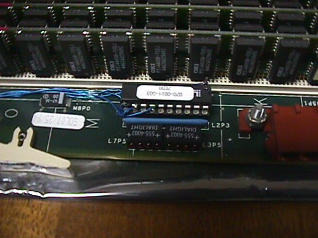
Part 1 - The 20 pin PAL just near the IP17 power
connector
 Power connector is just to the right, SIMM bank behind, top clip to the
left.
Power connector is just to the right, SIMM bank behind, top clip to the
left.
There are four wires running from the chip with the white paper label
(which is 070-0814-003 with 7CD0 under this number). The first three are
visible in the full size image. The last one runs behind the chip to the
last leg on the right. For the purposes of this discussion, we'll number
the legs from front left in an anti-clockwise manner. Thus:
-
The left-most leg on the front of the chip (as we look at it here) - leg
1 - is removed from the socket and wire 1 is soldered to it.
-
Leg 2 has wire 2 soldered to it.
-
Leg 4 has wire 3 soldered to it.
-
The right most-leg on the back of the chip (again as shown in this view)
- leg 11 - is also removed from its socket and wire 4 is soldered to it.
Its possible that this PAL and the wires running from it in parts 2-4 are
something to do with supporting memory SIMM size (thanks to SkyWriter for
pointing this out) largely due to the fact that the PAL has the word MSIZE
or MEMSIZE typed onto its label on some IP17s. Let's hope so because
I still havent been able to work out which wire goes where in parts 2-4
:-(. Also, why does the R4400 board have a later rev than the R4000 board,
yet both support 8MB SIMMs? Perhaps the R4400 board has been modified to
support 16Mb SIMMs or maybe it had a fault which had to be patched - wish
I knew :-)
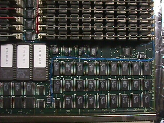
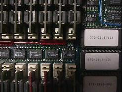
Part 2 - Where do the four wires go?
 The four wires go along the top of the IP17 from the chip shown in part
1. This picture is oriented such that the backplane connectors are parallel
with the bottom of the photo. Wire ? splits off from the rest just past
the SIMM bank and heads down to a chip between the two banks shown. Wires
?,? and ? continue down to the chips shown in part 3.
The four wires go along the top of the IP17 from the chip shown in part
1. This picture is oriented such that the backplane connectors are parallel
with the bottom of the photo. Wire ? splits off from the rest just past
the SIMM bank and heads down to a chip between the two banks shown. Wires
?,? and ? continue down to the chips shown in part 3.
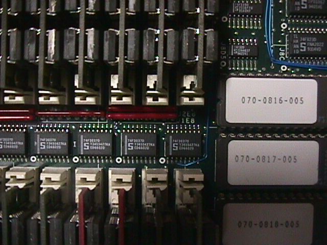
Part 3 - Three wires go here
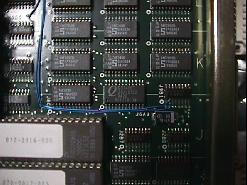 Wires ? and ? go to the same leg of the chip in the lower right of the
photo. Wire ? goes to a leg of the chip shown in the upper left of the
photo.
Wires ? and ? go to the same leg of the chip in the lower right of the
photo. Wire ? goes to a leg of the chip shown in the upper left of the
photo.
Part 4 - One wire goes here
 Wire ? goes to the leg of the chip shown in the centre of the photo.
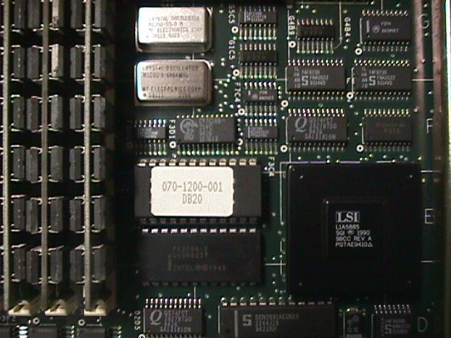
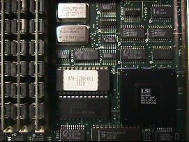
Part 5 - What the hell is this chip?
Thats almost it. Apart from the oscillator and the CPU (obviously) one
other chip is different. This chip is a removeable chip and it is in a
socket near location F3C4. On the R4400 board this chip is rev 070-1200-001
DB20 whilst on the R4000 board this chip is rev 070-0815-002 DA20. Anybody
know what this chip is and whether it makes a difference? If so then mail
me please.
Here's a picture of the chip and its surrounds just in case the location
number doesnt get you there. To orient youself, this picture is taken such
that the backplane connectors are parallel to the right hand side of the
image with the lower rear SIMM slot visible at the left.
 Power connector is just to the right, SIMM bank behind, top clip to the
left.
Power connector is just to the right, SIMM bank behind, top clip to the
left.