Systems
Origin 2000 / Onyx 2
Introduction
General
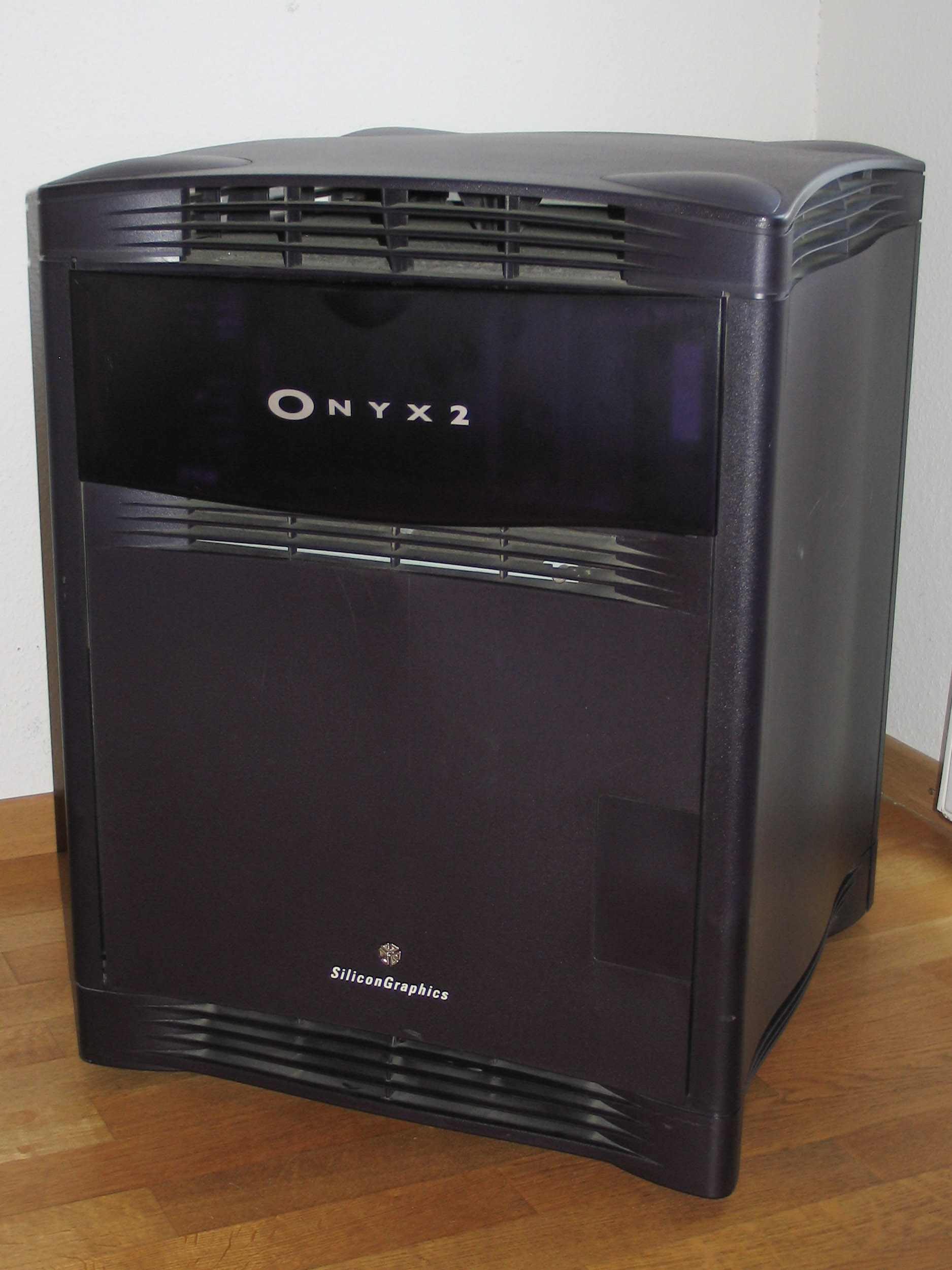
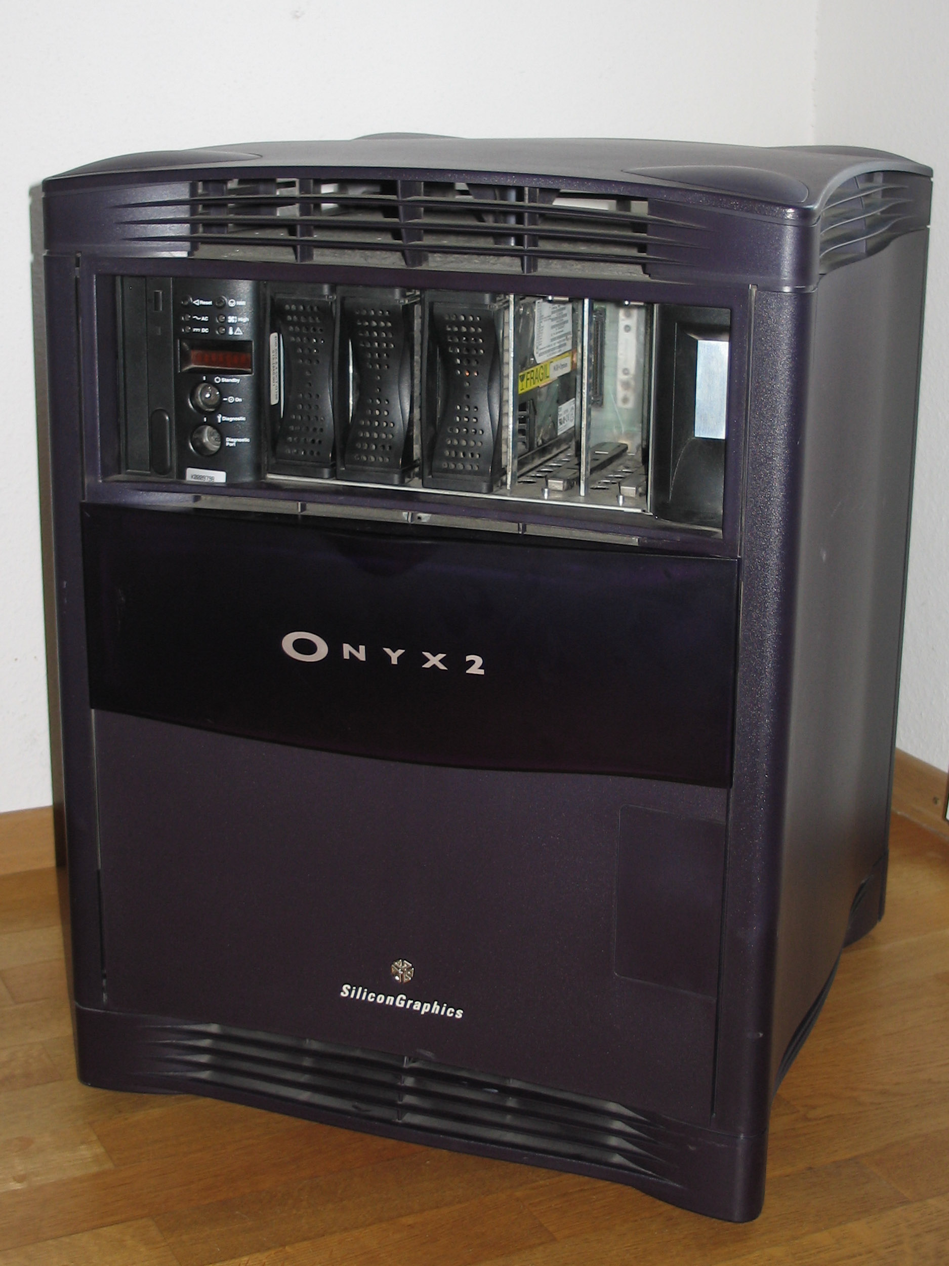
Front of an Onyx 2 system.
The Origin 2000 family replaced the Challenge and Power Challenge family of servers. Likewise the Onyx 2 is the successor to the Onyx line of graphics workstations.
They offer superior scalability ranging from 2 CPU deskside systems to large scale rackmount systems consisting of 128 CPUs in a single image system and expandung much further in high end supercomputing environments. The systems use Silicon Graphics’ distributed Scalable Shared-memory MultiProcessing architecture, which is called S2MP.
For lower demands a smaller and less scalable solution is available. The Origin 200 can expand to a maximum of 4 CPUs.
The graphics capable Onyx 2 is based on the same technology. The major differences are as follows:
- Deskside systems differ in the layout of the backplane that has slots for graphics hardware in the Onyx 2, where the Origin 2000 can be upgraded with further CPU boards.
- Rackmount systems of both kinds use the same compute modules (no graphics slots), the Onyx 2 has additional graphics modules.
- The IO board differs in the amount and kind of connections made available (IO6 vs. IO6G).
Regarding the visual design language the Origin 2000 is possibly the best designed server system that Silicon Graphics has ever produced. The racks still have enourmous size but the nice styling with blue and grey/silver parts make them look less intimidating than the old Challenge systems while still looking very impressing.
Configurations
Origin 2100
Deskside system without router support, 2-8 MIPS processors. The upgrade path from this system is somewhat limited. This is not only a marketing trick as Alexis Cousein points out in comp.sys.sgi.hardware: "[...] PROM changes, and a different part number (readable by IRIX) - to comply with export license restrictions, the SGI 2100 machines can *not* be shipped in a configuration that enables connecting them to an Origin 2000!" (Message-ID: <3E423ECC.25FD3879@sgi.com>).
Scalable Origin 2000 Systems
| Origin 2200 | Origin 2400 | Origin 2800 | Cray Origin | |
|---|---|---|---|---|
| Router | Null/Star Router | Standard Router | Standard Router | Cray Meta Router |
| Node Cards | 1-4 | 1-8 | 1-32 | 1-64 |
| Processors | 2-8 MIPS R1x000 CPU | 2-16 MIPS R1x000 CPU | 2-64 MIPS R1x000 CPU | 2-128 MIPSMIPS R1x000 CPU |
| Memory | 64 MB - 16 GB | 64 MB - 32 GB | 64 MB - 128 GB | 64 MB - 256 GB |
| I/O | 1 Base IO | 1-2 Base IO | 1-8 Base IO | 1-16 Base IO |
Onyx 2 Systems
History
- 1996
- Origin 2000 series introduced
Onyx 2 series introduced - 1998, February
- MIPS R10000 processors with 250 Mhz introduced to Origin 2000 series
- 1998, March
- MIPS R10000 processors with 250 Mhz introduced to Onyx 2 series
- 1999, July
- Origin 2100 introduced as midrange server for 2 to 8 processors
- 2000, April
- InfiniteReality 3 graphics announced and shipping
- 2002, January
- End of Production announced for 30 June 2002.
- 2002, June
- End of Production (Origin 2000)
- 2003, June
- End of Production (Onyx 2)
- 2007, June
- End of Service (Origin 2000)
- 2008, June
- End of Service (Onyx 2)
Architecture
Concept
Aside from higher performance among the design goals were increased scalability and modularity in comparison to previous SMP designs. The resulting concept is called Scalable Shared Memory Multiprocessor (S2MP). The key features include:
- Interconnection fabric to link nodes (NUMAlink)
- Crossbar architecture within main system ASICs (Hub, Router, Crossbow)
- Distributed shared memory and I/O
- Cache coherent shared memory
Memory Hierarchy
The Distributed Shared Memory architecture of Origin 2000 systems adds some further levels to the memory hierarchy. The following lists the memory hierarchy starting from the local processor.
- processor registers
- cache (on-chip 1st level, additional 2nd, 3rd... level)
- local memory (located on the nodeboard)
- remote memory (located on other nodeboards)
- remote cache
System Components
Origin 2000 systems are built of one or more of the following:
- Chassis (Midplane, etc.)
- Nodeboard (CPU, Memory, I/O, Interconnection, etc.)
- IO board and options (XIO, PCI, etc.)
- Routers
- Onyx 2 only: graphics option
Node Board
Processors
| CPU Board | Processor | Clockspeed | Cache (d/i) | Cache (2nd) | Floating Point |
|---|---|---|---|---|---|
| IP27 | R10000 | 180 MHz | 32kb / 32kb | 1MB | R10000 onboard |
| IP27 | R10000 | 195 MHz | 32kb / 32kb | 4MB | R10000 onboard |
| IP31 | R10000 | 250 MHz | 32kb / 32kb | 4MB | R10000 onboard |
| IP31 | R12000 | 300 MHz | 32kb / 32kb | 8MB | R12000 onboard |
| IP31 | R12000 | 350 MHz | 32kb / 32kb | 4MB | R12000 onboard |
| IP31 | R12000 | 400 MHz | 32kb / 32kb | 8MB | R12000 onboard |
| IP31 | R14000 | 500 MHz | 32kb / 32kb | 8MB | R12000 onboard |
Each of the nodeboards contains two processors.
It is possible to mix different types of nodeboards in one system. There are two exceptions/limitations:
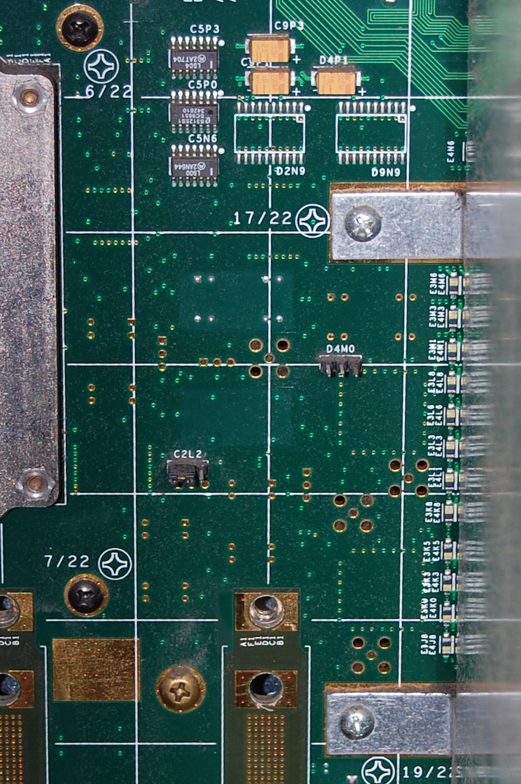
D4M0 / C2L2 Jumper
- The 180 MHz IP27 cannot be mixed with any other type of Nodeboard as it requires a different bus timing. A jumper on the backplane of the system needs to be moved to switch between the settings for 180 MHz nodeboards or any other type of nodeboard. The following table shows the setup of the jumper sets as seen from the back of the machine:
               180 MHz           Other

D4M0           [.|.].            . . .

C2L2            . . .           [.|.].
- The 350 MHz IP31 is limited in operation. It can only be used for systems of up to 8 CPUs and has only 4 MB of second level cache.
Memory
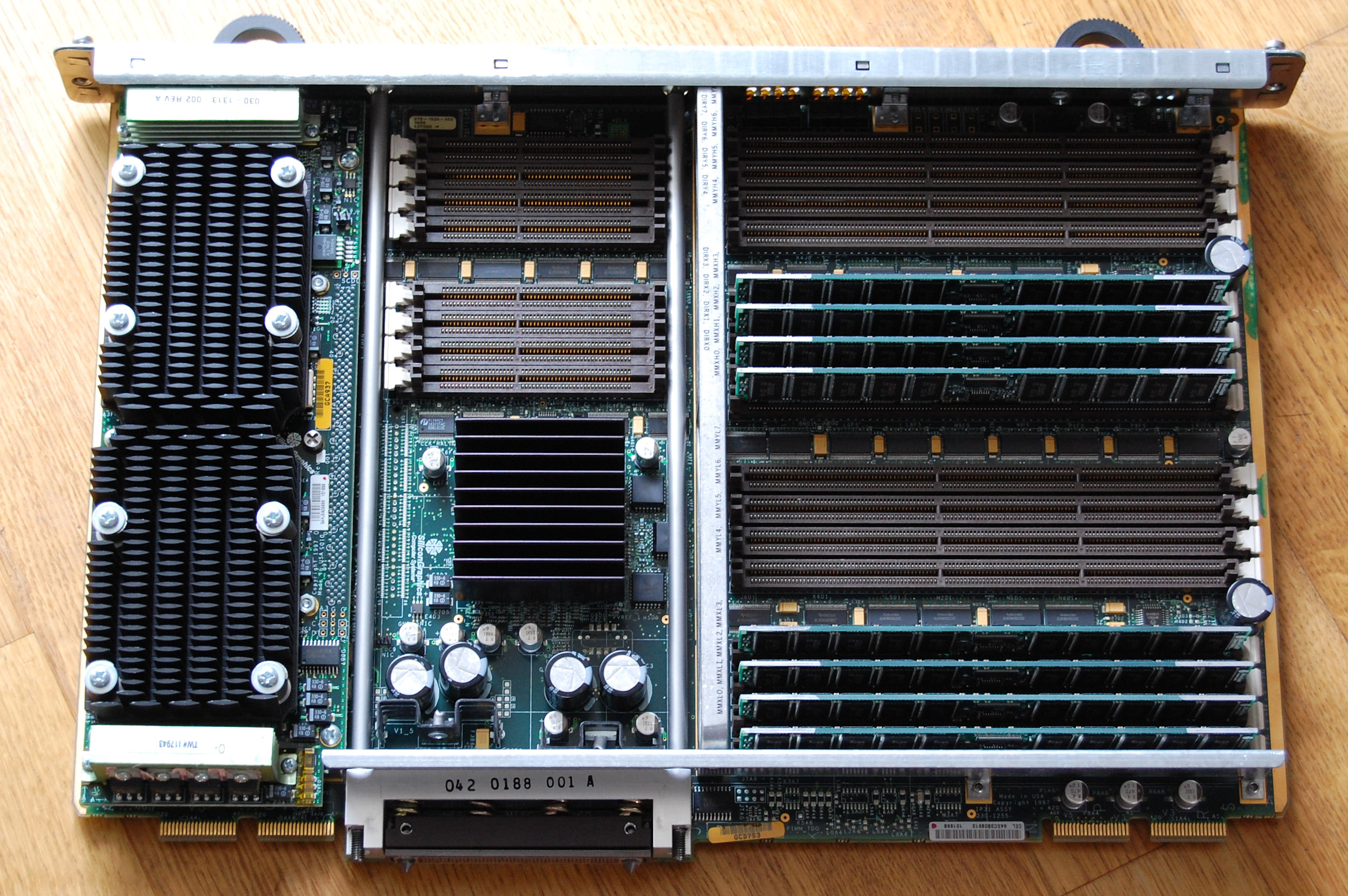
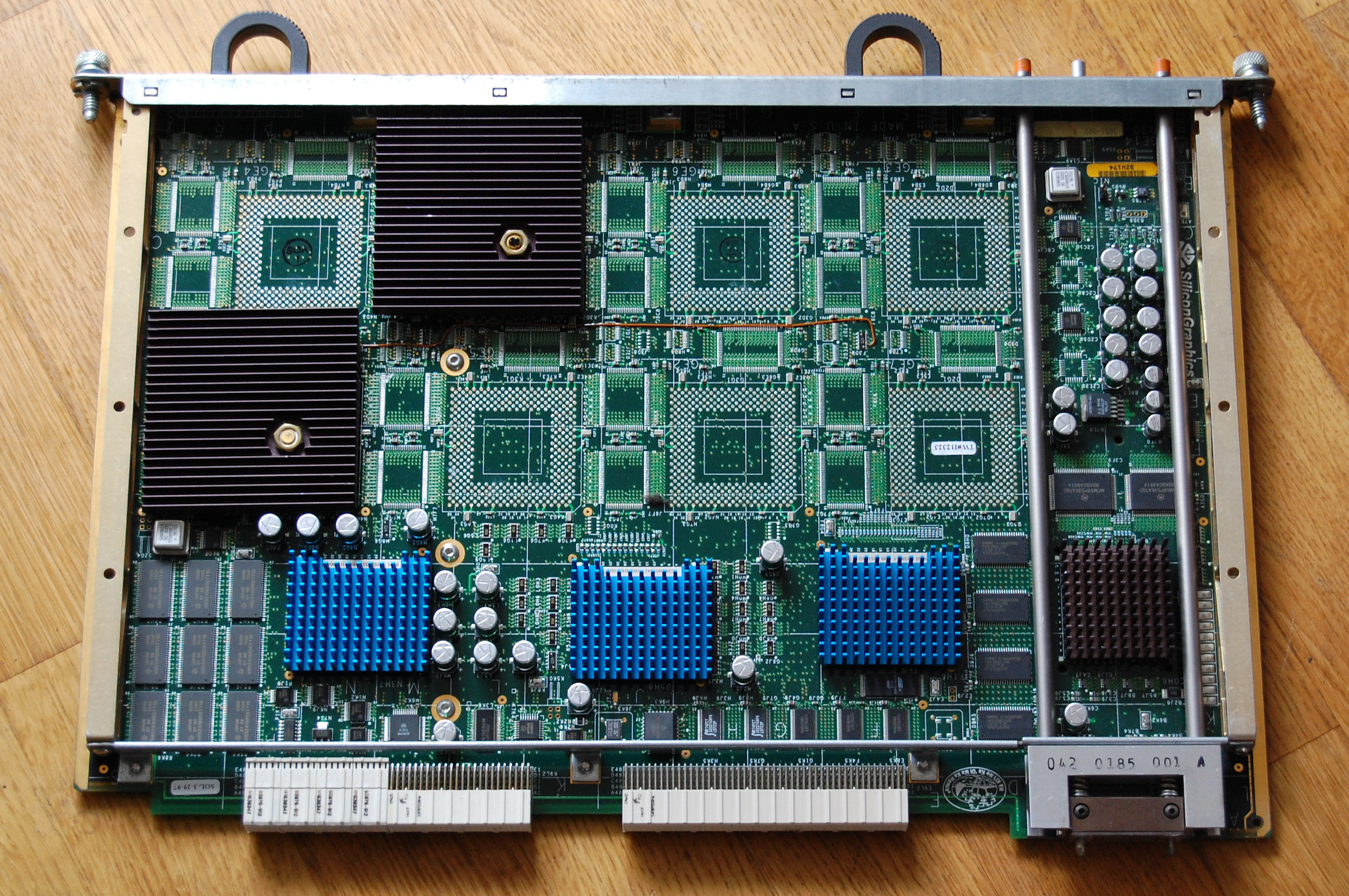
IP27 CPU board.
Type:                   DIMM, SDRAM
Sockets:                16 (8 * 2 sockets)

Minimum configuration:  2 modules
Maximum configuration:  4 GB (16 256 MB moduless (64MBit))
DIMMs are available in sizes of 16, 32, 64 and 256 MB. The memory modules used in the Origin 200 and Origin 2000 / Onyx 2 are of the same type.
For systems with more than 32 processors additional directory memory must be added into the 8 slots set aside for this purpose. For configurations up to 32 processors directory memory is included in the main memory.
Colors are used to distinguish between the different memory modules:
GREEN        64 MB
WHITE       128 MB
RED         256 MB
HUB
The Hub which is included on the nodeboard is a custom ASIC that connects the CPUs, memory, the IO subsystem and the system interconnection. It is a four-port crossbar switch that connects the following four interfaces:
- processor(s)
- memory
- XIO IO
- CrayLink interconnection
Status Display
The nodeboard has two columns of eight LEDs in two groups of four. Each of these columns is a status display for one of the CPUs installed on the nodeboard. They show diagnostic information during the POST of the system and serve as load meter when IRIX is running. The LEDs at the bottom are used to show a CPU heartbeat once IRIX has been loaded. A detailed overview of the LED messages can be found in the Nekochan Wiki.
IO Subsystem
IO6 Base IO Board
The base IO board contains some basic functionality of the Origin 2000 server:
- 1 10/100Base-TX Fast Ethernet link, with auto-negotiation (compliant with 802.3u)
- 2 460-Kbaud serial ports, composed of dual, independent UARTS
- 1 external, single-ended, wide UltraSCSI (compliant with X3.131-1994) port
- 1 internal Fast 20 UltraSCSI (compliant with X3.131-1994) single-ended port
- 1 real-time interrupt output for frame sync
- 1 real-time interrupt input (edge triggered)
- Flash PROM, NVRAM and Time-of-Day clock
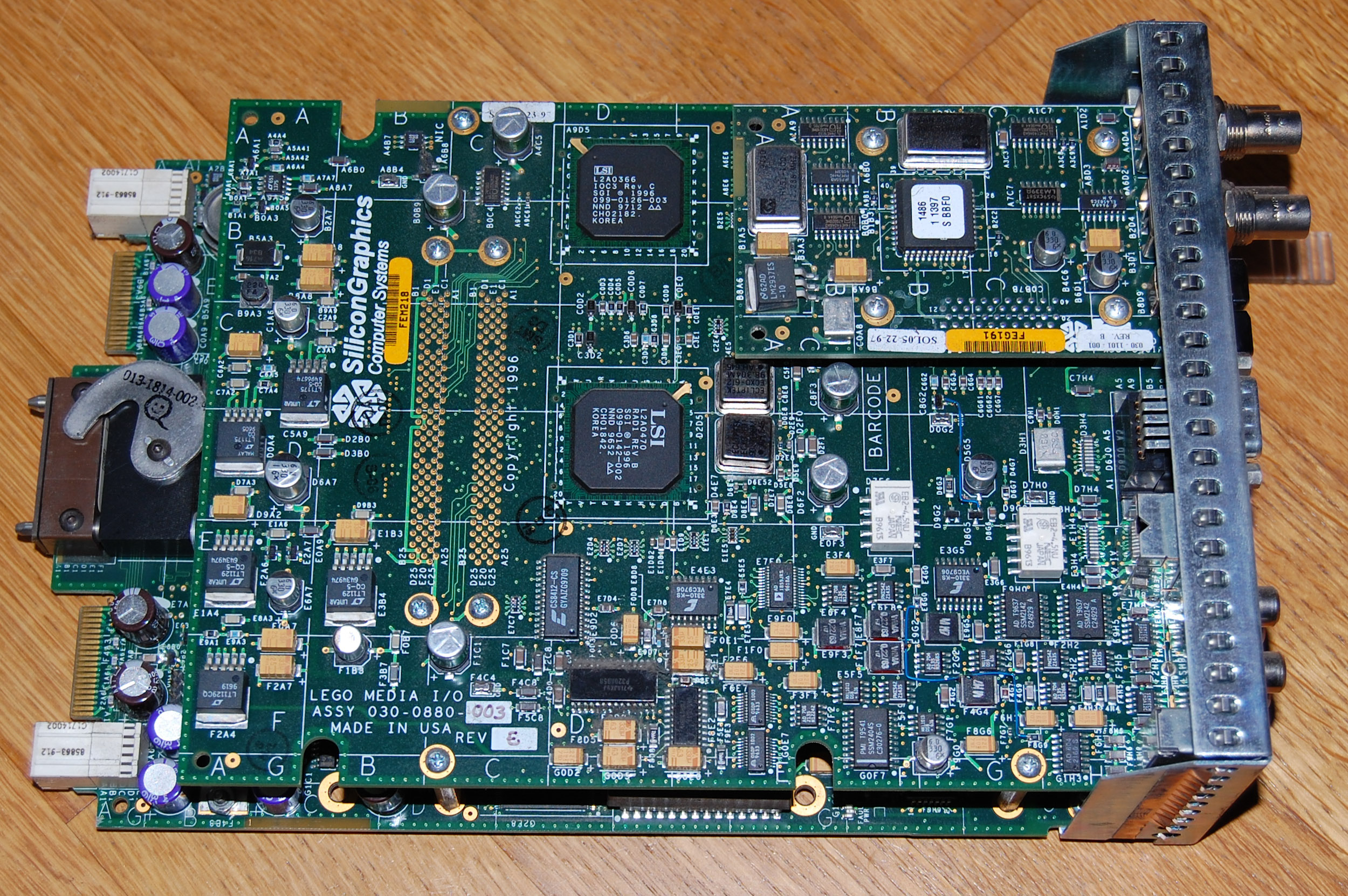
IO6G Base IO Board
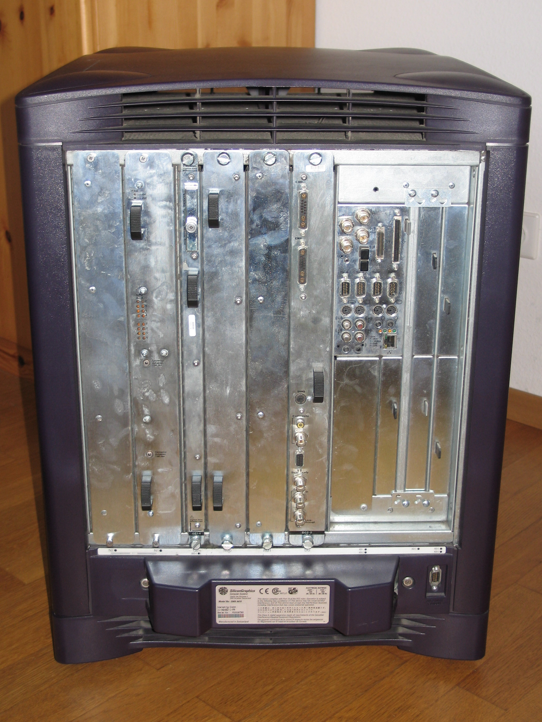
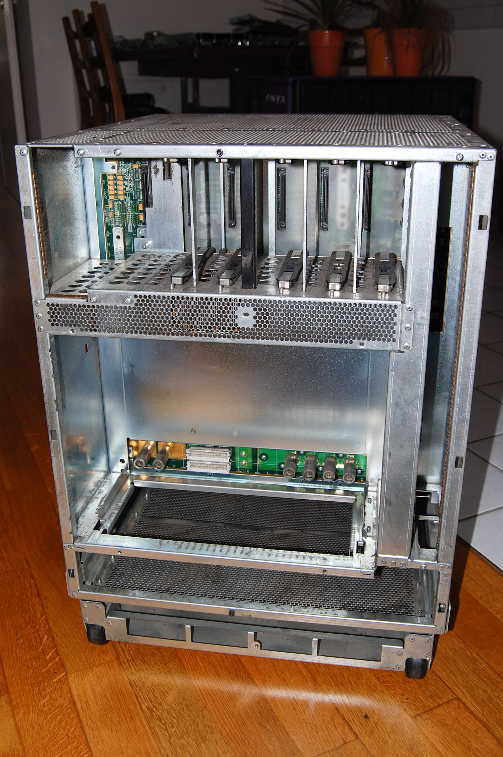
Back of the Onyx 2.
Compared to the base IO board of the Origin 2000 the one for the Onyx 2 includes additional functionality due to the nature of the system:
- 1 36-pin IEEE 1284-C compatible parallel port
- 4 nine-pin serial ports (each port software selects for RS-232 or RS-422 operation)
- 1 external, single-ended, wide UltraSCSI (compliant with X3.131-1994) port
- 1 internal Fast 20 UltraSCSI (compliant with X3.131-1994) single-ended port
- 2 sets ouf keyboard/mouse connectors (PS/2)
- 2 analog stereo input 2.5 mm RCA type jacks
- 2 analog stereo output 2.5 mm RCA type jacks
- 1 powered speaker 2.5 mm power jack
- 1 stereo headphone or powered speaker output 3.5 mm stereo jack
- 1 analog mono microphone input 3.5 mm jack
- 1 digital audio stereo input (AES-3id-1995) 75 ohm BNC jack
- 1 digital audio stereo output (AES-3id-1995) 75 ohm BNC jack
- 1 optical digital stereo input connector (eight-channel ADAT)
- 1 optical digital stereo output connector (eight-channel ADAT)
- 2 loop-through video sync 75-ohm BNC inputs
- 1 real-time interrupt output for frame sync
- 1 real-time interrupt input (edge triggered)
- Flash PROM, NVRAM and Time-of-Day clock
XIO Devices
XIO expansion options can be used in either Origin 2000 or Onyx 2 systems. The following is a selection of available options for the XIO expansion slots:
- Fast Ethernet and Serial ports (4x 10/100 Base-TX, 6 115kbps serial)
- Ultra SCSI (3 differential, 1 differential/single-ended interfaces)
- Fibre Channel (2 200 MB/s)
- ATM (4 OC3C 150 MB/s)
- HIPPI (1 100 MB/s)
XIO Bridges
In additon to native XIO devices options for other expansion buses can be used with Origin 2000 or Onyx systems. Additional bridge hardware is required for this purpose:
- PCI (internal expansion box, 3 64bit fullsize PCI slots; max. one per Origin 2000 module)
- VME64 (XIO interface board, 6U/9U VME system controller and CrayLink cable; maximum of 5 per module)
Graphics
Graphics Options
The Infinite Reality graphics options are not connected to the XIO slots. On deskside systems the midplane has special slots for graphics options that run through a K-Town to XIO interface. For non-deskside systems this connection requires an K-Town interface that expands the XIO interface to external devices (the graphics option in this case). The K-Town interface is a XIO option card that is required for rackmount Onyx 2 systems.
Video Options
- DMediaPro DM3 High-Definition and Standard-Definition video I/O option
The High Definition Graphics Video Output Option attaches to the DG5 board on Infinite Reality graphics subsystems in Onyx 2 and Onyx 3000. It consists of a TMDS video output daughtercard, a breakoutbox and a TMDS optional input. The video option offers real time graphics to video output in various high definition formats.
Interconnection
Router Boards
- Null Router
Connects 2 nodeboards in deskside systems. The null router does not have external connections and thus cannot be used for further expansion of the system. - Star Router
Connects up to four nodeboards in deskside systems. - Standard (Rack) Router
Connects to to 32 nodeboards located in 1 to 8 Origin 2000 modules. - (Cray) Meta Router
Expands system up to 64 nodeboards. Used in conjunction with standard routers.
Chassis
Deskside
The dimensions of a deskside Origin 2000 / Onyx 2:
width:     50,8 cm / 20.0"
height:    67,3 cm / 26.5"
depth:     61,0 cm / 24.0"

weight:    77,3 kg / 170 lbs (min.)
The deskside systems contains one Compute Module or an Onyx 2 deskside module.
Rackmount
The dimensions of a rackmount Origin 2000 / Onyx 2:
width:      53,0 cm / 26.0"
height:    185,0 cm / 73.0"
depth:     102,0 cm / 40.0"

weight:    317 kg / 700 lbs (min.)
The rackmount systems can hold more than one Compute Module or additional hardware like the Graphics Module used in Onyx 2 systems or RAID, JBOD enclosures.
A full rackmount system may use more than a single rack. Rackmount systems are usually equipped with one multimodule system controller (+ display) which can be used to issue commands for system as a whole - even if it spans multiple racks.
Compute Module
The compute module is used in Origin 2000 rackmount and deskside systems as well Onyx 2 rackmount systems. A compute module can contain:
- front accessible
- 1 5.25" slot for CD-ROM drive
- MSC - Module System Controller
- 5 slots for SCA harddisks
- 2 slots for router boards (2 router required for more than 2 nodeboards)
- accessible from the back
- 4 slots for nodeboards (slot 3-4 only available with two router boards)
- 12 XIO slots (slot 7-12 require at least a second nodeboard)
The various components are plugged into the midplane of the module.
Onyx 2 Deskside Module
The Onyx 2 Deskside Module is only used for Onyx 2 deskside systems which need to have the system as well as the graphics option in a single enclosure. Such a module contains:
- front accessible
- 1 5.25" slot for CD-ROM drive
- MSC - Module System Controller
- 5 slots for SCA harddisks
- Null Router installed
- accessible from the back
- 2 nodeboards
- graphics boardset (up to 2 RM)
- 6 XIO slots; one is occupied by the Base IO board, another one is used for interfacing to the graphics option
The individual components of the system are plugged into the midplane.
Graphics Module
The graphics module can contain up to two Infinite Reality graphics options:
- accessible from the back
- Infinite Reality with 2 Raster Managers
- Infinite Reality with 4 Raster Managers
- KTOWN board
The graphics boards are plugged into the midplane of the graphics module.
Specials
WebFORCE
Silicon Graphics sold the WebFORCE Origin 2000 as a scalable line of dedicated inter-/intranet servers. The WebFORCE systems came with a special software bundle for Inter- and Intranet solutions:
- Netscape Enterprise server 2.0
- Silicon Graphics WebMeter
- Intranet Junction
Rugged Version
CRI, a division of RSI Inc., is building rugged rackmount versions of this system.
Problems
Operating System
Choosing an operating system.
When the Origin line was introduced the system specific IRIX 6.4 was released. Later models may require a different OS release to support the hardware. The systems are also supported by IRIX 6.5 including the final release IRIX 6.5.30.
Regardless of the system configuration it is always recommended to use IRIX 6.5.30.
Pictures
Onyx 2
Front of an Onyx 2 system.
Onyx 2 with opened front door.
Back of the Onyx 2.
Stripped onyx (front side).

Stripped Onyx (back side).

IP27 CPU board.
IP27 CPU board.
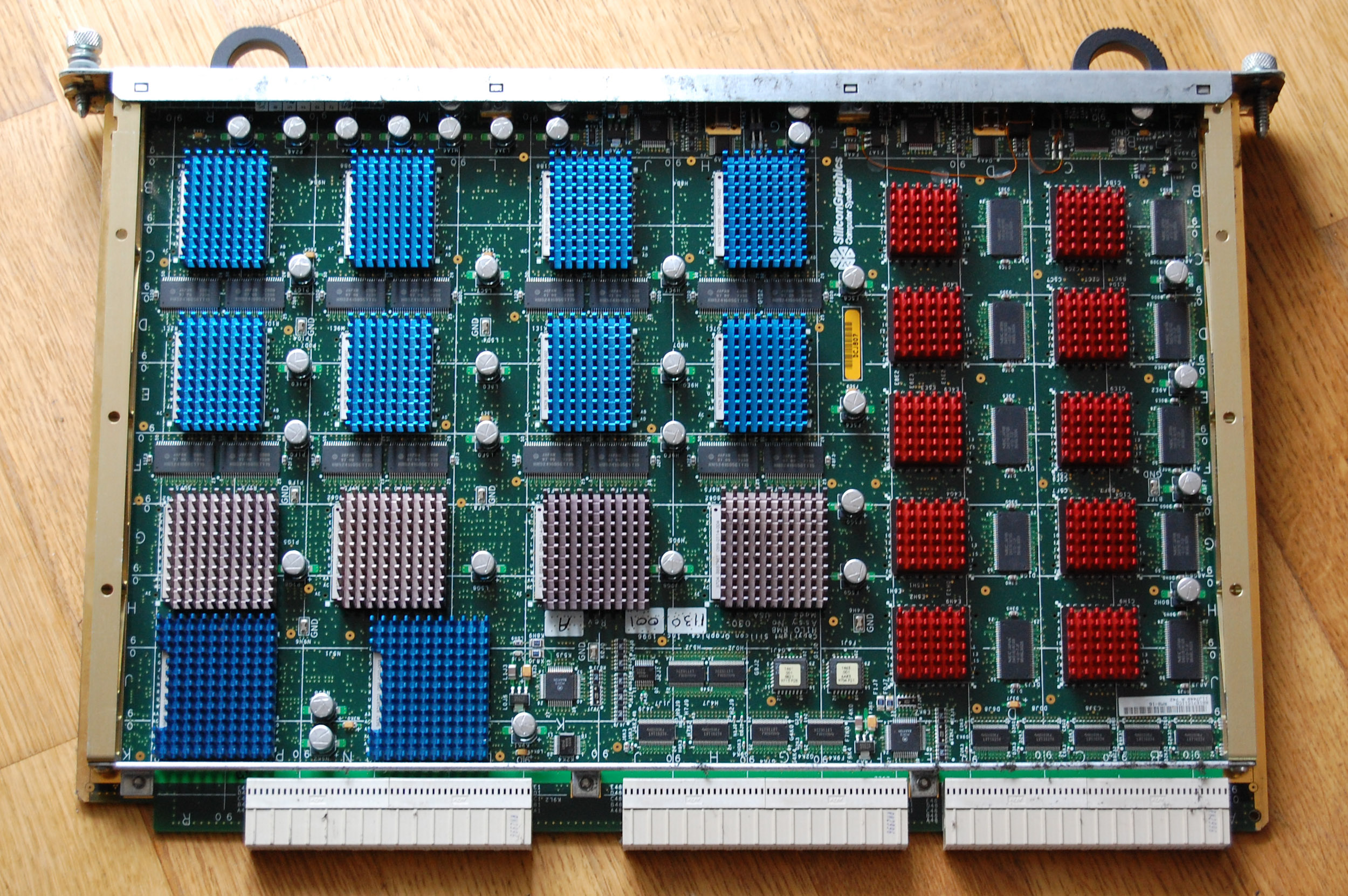
GE14-2 Geometry Engine board.
RM8-16 Raster Manager board.

DG5-2 Display Generator board.
IO6G IO Controller.
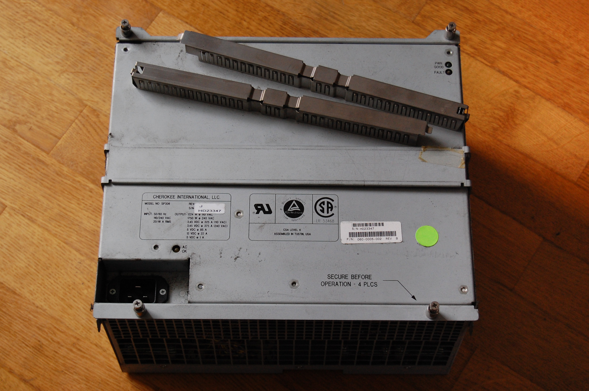
Powersupply (front)

Powersupply (back)
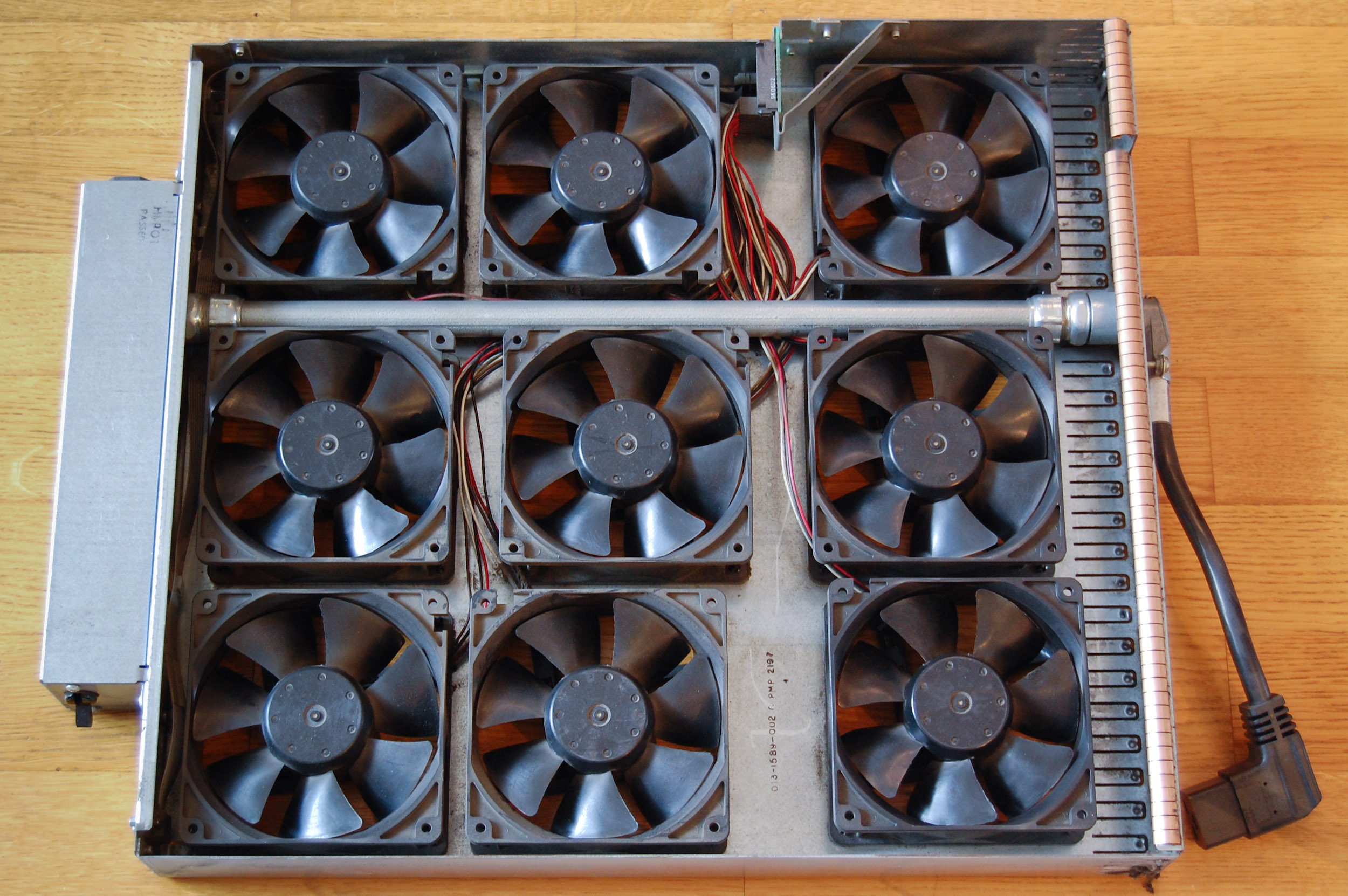
Fan drawer.
D4M0 / C2L2 Jumper
Links
Manuals
- Origin and Onyx 2 Theory of Operations Manual
- Site Preparation for SGI 2000-Series, Origin, Onyx 2, Octane, and O2 [local]
- Origin 2000 Deskside Owner's Guide
- Origin 2000 Rackmount Owner's Guide
- Onyx 2 Deskside Workstation Owners Guide
- Onyx 2 Rackmount Owners Guide
- SGI 2100 Server Owner's Guide
- SGI 2200 Server Owner's Guide
- SGI 2400 and 2800 Server Owner's Guide
- InfiniteReality4 Addendum to Silicon Graphics Onyx2, SGI Onyx 3000 Series, and SGI Onyx 300 Guides
Articles
- Here comes cc-NUMA
Presentation by Forest Baskett, USENIX August 1998
Websites
- Futuretech: Origin - Ian Maplesons Origin page
- Futuretech: Onyx 2 - Ian Maplesons Onyx 2 page